HP Server rp8420 HP 9000 rp8420 Server - User Service Guide, Fifth Edition - Page 25
PDH Riser Board, Central Processor Units, Memory Subsystem
 |
View all HP Server rp8420 manuals
Add to My Manuals
Save this manual to your list of manuals |
Page 25 highlights
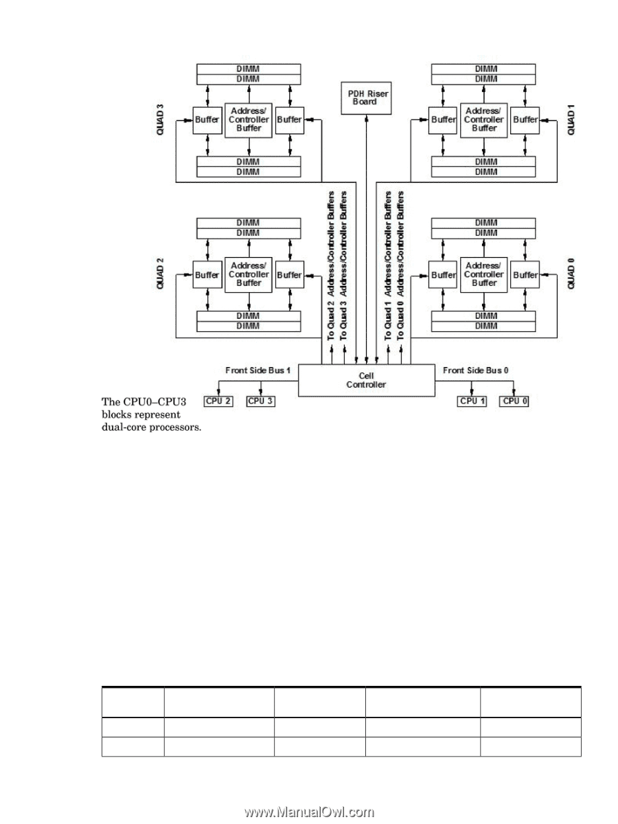
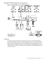
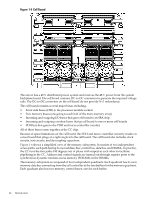
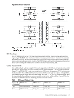
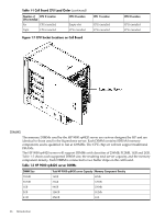
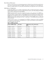
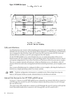
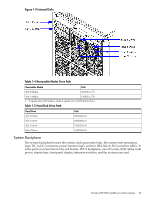
Figure 1-6 Memory Subsystem PDH Riser Board The HP 9000 rp8420 server PDH riser board is a small card that plugs into the cell board at a right angle. The PDH riser interface contains a microprocessor memory interface microcircuit, hardware including the processor-dependant code (PDC) flash memory, and a manageability microcontroller with associated circuitry. The PDH obtains cell board configuration information from cell board signals and from the cell board local power module (LPM). Central Processor Units The cell board will hold up to eight CPUs and is populated with CPUs in increments of two after meeting the minimum of two CPUs installed on the cell board. Each CPU socket designated in Figure 1-7 as CPU 0, CPU 1, and so on contains two CPUs since there are two CPUs per processor module socket. On a cell board, the processors must be the same type and speed. For a partition, the processors must be the same type and speed. See Table 1-1 for the CPU load order that must be maintained when adding a processor module socket to the cell board. See Figure 1-7 for the locations on the cell board for installing processor module sockets. Table 1-1 Cell Board CPU Load Order Number of CPU 2 Location CPUs Installed Two Terminator installed Four CPUs installed CPU 3 Location Empty slot Empty slot CPU 1 Location Empty slot Empty slot CPU 0 Location CPUs installed CPUs installed Detailed HP 9000 rp8420 server Description 25
-
 1
1 -
2
-
3
-
4
-
5
-
6
-
7
-
8
-
9
-
10
-
11
-
12
-
13
-
14
-
15
-
16
-
17
-
18
-
19
-
 20
20 -
 21
21 -
 22
22 -
 23
23 -
 24
24 -
 25
25 -
 26
26 -
 27
27 -
 28
28 -
 29
29 -
 30
30 -
31
-
32
-
33
-
34
-
35
-
36
-
37
-
38
-
39
-
40
-
41
-
42
-
43
-
44
-
45
-
46
-
47
-
48
-
49
-
50
-
51
-
52
-
53
-
54
-
55
-
56
-
57
-
58
-
59
-
60
-
61
-
62
-
63
-
64
-
65
-
66
-
67
-
68
-
69
-
70
-
71
-
72
-
73
-
74
-
75
-
76
-
77
-
78
-
79
-
80
-
81
-
82
-
83
-
84
-
85
-
86
-
87
-
88
-
89
-
90
-
91
-
92
-
93
-
94
-
95
-
96
-
97
-
98
-
99
-
100
-
101
-
102
-
103
-
104
-
105
-
106
-
107
-
108
-
109
-
110
-
111
-
112
-
113
-
114
-
115
-
116
-
117
-
118
-
119
-
120
-
121
-
122
-
123
-
124
-
125
-
126
-
127
-
128
-
129
-
130
-
131
-
132
-
133
-
134
-
135
-
136
-
137
-
138
-
139
-
140
-
141
-
142
-
143
-
144
-
145
-
146
-
147
-
148
-
149
-
150
-
151
-
152
-
153
-
154
-
155
-
156
-
157
-
158
-
159
-
160
-
161
-
162
-
163
-
164
-
165
-
166
-
167
-
168
-
169
-
170
-
171
-
172
-
173
-
174
-
175
-
176
-
177
-
178
-
179
-
180
-
181
-
182
-
183
-
184
-
185
-
186
-
187
-
188
-
189
-
190
-
191
-
192
-
193
-
194
-
195
-
196
-
197
-
198
-
199
-
200
-
201
-
202
-
203
-
204
-
205
-
206
-
207
-
208
-
209
-
210
-
211
-
212
-
213
-
214
-
215
 |
 |