HP Server rp8420 HP 9000 rp8420 Server - User Service Guide, Fifth Edition - Page 185
D Templates, Equipment Footprint Templates, Computer Room Layout Plan
 |
View all HP Server rp8420 manuals
Add to My Manuals
Save this manual to your list of manuals |
Page 185 highlights
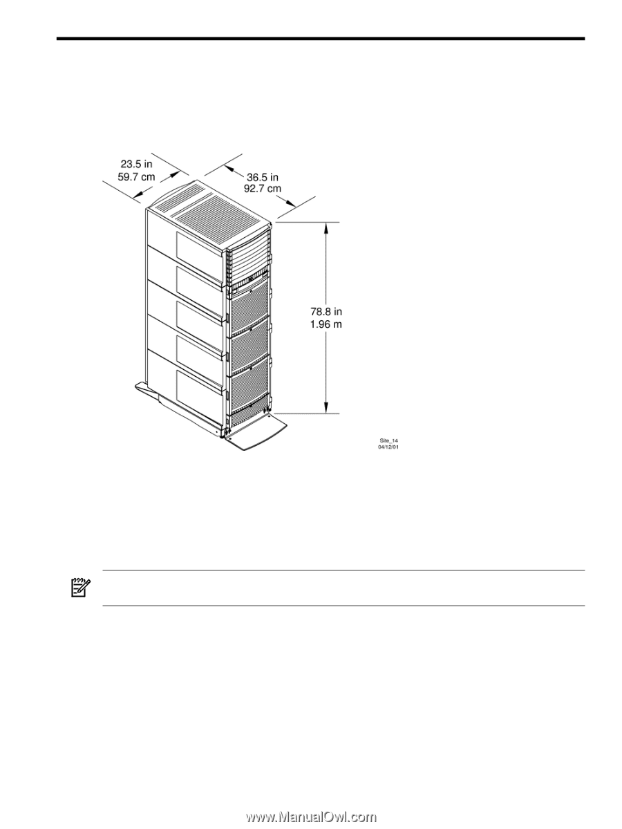
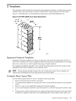
D Templates This appendix contains blank floor plan grids and equipment templates. Combine the necessary number of floor plan grid sheets to create a scaled version of the computer room floor plan. Figure D-1 illustrates the overall dimensions required for an HP 9000 rp8420 server. Figure D-1 HP 9000 rp8420 server Space Requirements Equipment Footprint Templates Equipment footprint templates are drawn to the same scale as the floor plan grid (1/4 inch = 1 foot). These templates show basic equipment dimensions and space requirements for servicing. The service areas shown on the template drawings are lightly shaded. The equipment templates should be used with the floor plan grid to define the location of the equipment that will be installed in your computer room. NOTE: Photocopying typically changes the scale of drawings copied. If any templates are copied, then all templates and floor plan grids must also be copied. Computer Room Layout Plan Use the following procedure to create a computer room layout plan: 1. Remove several copies of the floor plan grid. 2. Cut and join them together (as necessary) to create a scale model floor plan of your computer room. 3. Remove a copy of each applicable equipment footprint template. 4. Cut out each template selected in step 3; then place it on the floor plan grid created in step 2. 5. Position pieces until the desired layout is obtained; then fasten the pieces to the grid. Mark locations of computer room doors, air-conditioning floor vents, utility outlets, and so on. Equipment Footprint Templates 185
-
 1
1 -
2
-
3
-
4
-
5
-
6
-
7
-
8
-
9
-
10
-
11
-
12
-
13
-
14
-
15
-
16
-
17
-
18
-
19
-
20
-
21
-
22
-
23
-
24
-
25
-
26
-
27
-
28
-
29
-
30
-
31
-
32
-
33
-
34
-
35
-
36
-
37
-
38
-
39
-
40
-
41
-
42
-
43
-
44
-
45
-
46
-
47
-
48
-
49
-
50
-
51
-
52
-
53
-
54
-
55
-
56
-
57
-
58
-
59
-
60
-
61
-
62
-
63
-
64
-
65
-
66
-
67
-
68
-
69
-
70
-
71
-
72
-
73
-
74
-
75
-
76
-
77
-
78
-
79
-
80
-
81
-
82
-
83
-
84
-
85
-
86
-
87
-
88
-
89
-
90
-
91
-
92
-
93
-
94
-
95
-
96
-
97
-
98
-
99
-
100
-
101
-
102
-
103
-
104
-
105
-
106
-
107
-
108
-
109
-
110
-
111
-
112
-
113
-
114
-
115
-
116
-
117
-
118
-
119
-
120
-
121
-
122
-
123
-
124
-
125
-
126
-
127
-
128
-
129
-
130
-
131
-
132
-
133
-
134
-
135
-
136
-
137
-
138
-
139
-
140
-
141
-
142
-
143
-
144
-
145
-
146
-
147
-
148
-
149
-
150
-
151
-
152
-
153
-
154
-
155
-
156
-
157
-
158
-
159
-
160
-
161
-
162
-
163
-
164
-
165
-
166
-
167
-
168
-
169
-
170
-
171
-
172
-
173
-
174
-
175
-
176
-
177
-
178
-
179
-
 180
180 -
 181
181 -
 182
182 -
 183
183 -
 184
184 -
 185
185 -
 186
186 -
 187
187 -
 188
188 -
 189
189 -
 190
190 -
191
-
192
-
193
-
194
-
195
-
196
-
197
-
198
-
199
-
200
-
201
-
202
-
203
-
204
-
205
-
206
-
207
-
208
-
209
-
210
-
211
-
212
-
213
-
214
-
215
 |
 |