HP Server rp8420 HP 9000 rp8420 Server - User Service Guide, Fifth Edition - Page 149
Replacing a VRM, Removing and Replacing the Core I/O, Cell Board Power LED, CAUTION
 |
View all HP Server rp8420 manuals
Add to My Manuals
Save this manual to your list of manuals |
Page 149 highlights
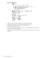
Figure 6-41 Cell Board Power LED 4. Press each extraction lever and slide the lock to the unlocked position. Pull the extraction levers outward to unseat the cell board from the backplane connector. See Figure 6-16 (page 117). 5. Slide the cell board from the chassis. See Figure 6-19 (page 119). 6. Remove the memory and CPU covers. 7. Locate the VRM to be replaced. 8. Loosen the VRM retaining screws. 9. Pull the VRM off the cell board. Replacing a VRM 1. Insert the new VRM into the socket. CAUTION: Check for proper pin orientation before inserting VRM. 2. Tighten the screws until snug but do not over tighten. 3. Replace cell board memory and CPU covers. 4. Insert the cell board into the chassis. 5. Restore power to the cell board and test. 6. Install the right side cover. See "Replacing the Side Cover" (page 107). Removing and Replacing the Core I/O The core I/O is located in the rear of the chassis. There can be two core I/O boards installed in the server, core I/O 0 and core I/O 1. The core I/O can be replaced while standby power is applied. However, the operating system on the nPartition must be shut down to replace the FRU. Removing and Replacing the Core I/O 149
-
 1
1 -
2
-
3
-
4
-
5
-
6
-
7
-
8
-
9
-
10
-
11
-
12
-
13
-
14
-
15
-
16
-
17
-
18
-
19
-
20
-
21
-
22
-
23
-
24
-
25
-
26
-
27
-
28
-
29
-
30
-
31
-
32
-
33
-
34
-
35
-
36
-
37
-
38
-
39
-
40
-
41
-
42
-
43
-
44
-
45
-
46
-
47
-
48
-
49
-
50
-
51
-
52
-
53
-
54
-
55
-
56
-
57
-
58
-
59
-
60
-
61
-
62
-
63
-
64
-
65
-
66
-
67
-
68
-
69
-
70
-
71
-
72
-
73
-
74
-
75
-
76
-
77
-
78
-
79
-
80
-
81
-
82
-
83
-
84
-
85
-
86
-
87
-
88
-
89
-
90
-
91
-
92
-
93
-
94
-
95
-
96
-
97
-
98
-
99
-
100
-
101
-
102
-
103
-
104
-
105
-
106
-
107
-
108
-
109
-
110
-
111
-
112
-
113
-
114
-
115
-
116
-
117
-
118
-
119
-
120
-
121
-
122
-
123
-
124
-
125
-
126
-
127
-
128
-
129
-
130
-
131
-
132
-
133
-
134
-
135
-
136
-
137
-
138
-
139
-
140
-
141
-
142
-
143
-
 144
144 -
 145
145 -
 146
146 -
 147
147 -
 148
148 -
 149
149 -
 150
150 -
 151
151 -
 152
152 -
 153
153 -
 154
154 -
155
-
156
-
157
-
158
-
159
-
160
-
161
-
162
-
163
-
164
-
165
-
166
-
167
-
168
-
169
-
170
-
171
-
172
-
173
-
174
-
175
-
176
-
177
-
178
-
179
-
180
-
181
-
182
-
183
-
184
-
185
-
186
-
187
-
188
-
189
-
190
-
191
-
192
-
193
-
194
-
195
-
196
-
197
-
198
-
199
-
200
-
201
-
202
-
203
-
204
-
205
-
206
-
207
-
208
-
209
-
210
-
211
-
212
-
213
-
214
-
215
 |
 |
