HP Spectre 13-af000 Maintenance and Service Guide
HP Spectre 13-af000 Manual
 |
View all HP Spectre 13-af000 manuals
Add to My Manuals
Save this manual to your list of manuals |
HP Spectre 13-af000 manual content summary:
- HP Spectre 13-af000 | Maintenance and Service Guide - Page 1
Maintenance and Service Guide HP Spectre 13 Laptop PC IMPORTANT! This document is intended for HP authorized service providers only. - HP Spectre 13-af000 | Maintenance and Service Guide - Page 2
HP products and services are set forth in the express warranty statements accompanying such products and services. Nothing herein should be construed as constituting an additional warranty. HP guides, go to http://www.hp.com/support, and follow the instructions to find your product. Then select User - HP Spectre 13-af000 | Maintenance and Service Guide - Page 3
Safety warning notice WARNING! To reduce the possibility of heat-related injuries or of overheating the device, do not place the device directly on your lap or obstruct the device air vents. Use the device only on a hard, flat surface. Do not allow another hard surface, such as an adjoining optional - HP Spectre 13-af000 | Maintenance and Service Guide - Page 4
iv Safety warning notice - HP Spectre 13-af000 | Maintenance and Service Guide - Page 5
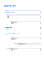
...10 Special keys ...11 Bottom ...12 3 Illustrated parts catalog ...13 Labels ...14 Computer components ...15 Miscellaneous parts ...20 4 Removal and replacement preliminary requirements ...24 Tools required ...24 Service considerations ...24 Plastic parts ...24 Cables and connectors ...25 Drive - HP Spectre 13-af000 | Maintenance and Service Guide - Page 6
...54 Updating Setup Utility (BIOS) ...54 Determining the BIOS version ...54 Downloading a BIOS update ...55 7 Using HP PC Hardware Diagnostics (UEFI) ...56 Downloading HP PC Hardware Diagnostics (UEFI) to a USB device 57 8 Specifications ...58 9 Backing up, restoring, and recovering ...59 Creating - HP Spectre 13-af000 | Maintenance and Service Guide - Page 7
Index ...67 vii - HP Spectre 13-af000 | Maintenance and Service Guide - Page 8
viii - HP Spectre 13-af000 | Maintenance and Service Guide - Page 9
Graphics Panel Memory Storage Audio and video Description HP Spectre 13 Laptop PC (model number 13-af0xx and 13-af1xx) ● Intel® Core™ i7-8565U 1.80 4 × 4 pieces) 8192-MB (256-MB × 16 × 4 × 4 pieces) Support for the following solid-state drives: ● 2-TB, M.2 2280-SATA-3/DS, Peripheral Component - HP Spectre 13-af000 | Maintenance and Service Guide - Page 10
Audio and video (continued) Wireless Ports Keyboard/pointing devices Power requirements Description Bang & Olufsen Support for dual speakers Support for HP Audio Boost 2.0 (with discrete amplifier) Camera: HP Wide Vision HD infrared camera with indicator light, 2 infrared lights, USB 2.0, HD BSI - HP Spectre 13-af000 | Maintenance and Service Guide - Page 11
requirements (continued) Sensors Security Operating system Serviceability Description Support for the following AC adapters: ● 65 finish ● 65-W AC adapter (non-PFC, USB Type-C) in dark ash silver finish Support for a 1.00-m power cord with a C5 connector Infrared thermal Trusted platform module 2.0 - HP Spectre 13-af000 | Maintenance and Service Guide - Page 12
2 Computer external components Your computer features top-rated components. This chapter provides details about your components, where they're located, and how they work. Locating hardware To find out what hardware is installed on your computer: ▲ Type device manager in the taskbar search box, and - HP Spectre 13-af000 | Maintenance and Service Guide - Page 13
required. - or - Connects a display device that has a USB Type-C connector, providing display output. NOTE: Your computer may also support a Thunderbolt docking station. Audio-out (headphone)/Audio-in (microphone) combo jack Connects optional powered stereo speakers, headphones, earbuds, a headset - HP Spectre 13-af000 | Maintenance and Service Guide - Page 14
. For additional safety information, refer to the Regulatory, Safety, and Environmental Notices. To access this guide: ▲ Select the Start button, select HP Help and Support, and then select HP Documentation. NOTE: When a device is connected to the jack, the computer speakers are disabled. 6 Chapter - HP Spectre 13-af000 | Maintenance and Service Guide - Page 15
obstructions. For wireless regulatory notices, see the section of the Regulatory, Safety, and Environmental Notices that applies to your country or region. To access this guide: ▲ Select the Start button, select HP Help and Support, and then select HP Documentation. Display 7 - HP Spectre 13-af000 | Maintenance and Service Guide - Page 16
Keyboard area TouchPad Component (1) TouchPad zone (2) Left TouchPad button (3) Right TouchPad button Description Reads your finger gestures to move the pointer or activate items on the screen. Functions like the left button on an external mouse. Functions like the right button on an - HP Spectre 13-af000 | Maintenance and Service Guide - Page 17
Lights Component (1) Power light (2) Caps lock light (3) Mute light Description ● On: The computer is on. ● Blinking: The computer is in the Sleep state, a power-saving state. The computer shuts off power to the display and other unneeded components. ● Off: The computer is off or in - HP Spectre 13-af000 | Maintenance and Service Guide - Page 18
Button and speakers Component (1) Power button (2) Speakers Description ● When the computer is off, press the button to turn on the computer. ● When the computer is on, press the button briefly to initiate Sleep. ● When the computer is in the Sleep state, press the button briefly to exit Sleep - HP Spectre 13-af000 | Maintenance and Service Guide - Page 19
Special keys Component (1) (2) (3) esc key fn key Windows key (4) Action keys Description Displays system information when pressed in combination with the fn key. Executes specific functions when pressed in combination with another key. Opens the Start menu. NOTE: Pressing the Windows key again - HP Spectre 13-af000 | Maintenance and Service Guide - Page 20
Bottom Component Vents Description Enable airflow to cool internal components. NOTE: The computer fan starts up automatically to cool internal components and prevent overheating. It is normal for the internal fan to cycle on and off during routine operation. 12 Chapter 2 Computer external - HP Spectre 13-af000 | Maintenance and Service Guide - Page 21
3 Illustrated parts catalog NOTE: HP continually improves and changes product parts. For complete and current information on supported parts for your computer, go to http://partsurfer.hp.com, select your country or region, and then follow the on-screen instructions. 13 - HP Spectre 13-af000 | Maintenance and Service Guide - Page 22
information that may be needed when troubleshooting system problems or travelling internationally with the computer. IMPORTANT: Check the following locations for the labels described in this section: the bottom of the computer, inside the battery bay, under the service door, on the back of the - HP Spectre 13-af000 | Maintenance and Service Guide - Page 23
Computer components Computer components 15 - HP Spectre 13-af000 | Maintenance and Service Guide - Page 24
Item Component Spare part number (1) 13.3-inch., TouchScreen display/top cover assembly (includes display panel cable and wireless antenna cables): Equipped with a UHD display assembly, an infrared HD webcam, narrow bezel, - HP Spectre 13-af000 | Maintenance and Service Guide - Page 25
Item Component For use in Saudi Arabia For use in South Korea For use in Spain For use in Switzerland For use in Taiwan For use in Thailand For use in Turkey For use in the United Kingdom For use in the United States In dark ash silver finish: For use in Belgium For use in Canada For - HP Spectre 13-af000 | Maintenance and Service Guide - Page 26
Item Component Spare part number (3) Keyboard shield (included with keyboard spare part kit) Keyboard Screw Kit (not illustrated, includes 54 keyboard screws) L04545-001 Speakers (include cables): (4a) Left speaker (includes cable and adhesive) 941847-001 (4b) Right speaker (includes - HP Spectre 13-af000 | Maintenance and Service Guide - Page 27
Item (9a) (8b) (10a) (10b) (11a) (11b) (12a) (12b) (13) (14) (15) Component Equipped with an Intel Core i5-8265U 1.60-GHz (turbo up to 3.90-GHz) quad-core processor (2400-MHz, 6.0-MB L3 cache, - HP Spectre 13-af000 | Maintenance and Service Guide - Page 28
Miscellaneous parts Component AC adapter: 65-W AC adapter (non-PFC, USB Type-C) in ceramic white finish 65-W AC adapter (non-PFC, USB Type-C) in dark ash silver finish 65-W AC adapter (non-PFC, USB Type-C) in ceramic white finish 65-W AC adapter (non-PFC, USB Type-C) in dark ash silver finish Duck - HP Spectre 13-af000 | Maintenance and Service Guide - Page 29
Component For use in the People's Republic of China For use in South Korea For use in the United Kingdom HP 13.3-inch. sleeve: In black finish In gray finish HP USB Type-C adapter: USB Type-C-to-HDMI adapter USB Type-C-to-HDMI 2.0 adapter USB Type-C-to-MultiPort hub USB Type-C-to-RJ45 adapter - HP Spectre 13-af000 | Maintenance and Service Guide - Page 30
Component For use in Japan For use in North America For use in the People's Republic of China For use in South Africa For use in Switzerland For use in Taiwan For use in Thailand For use in the United Kingdom Power cord (C5 connector, 1.00-m, FDH, Prime, Sticker): For use in Australia For use in - HP Spectre 13-af000 | Maintenance and Service Guide - Page 31
Component For use in the United Kingdom Power cord (C5 connector, 1.00-m, DH, FX, PRM, TAG): For use in Europe For use in North America For use in the United Kingdom Rubber Foot Kit (includes bottom cover rear foot strip): In ceramic white finish In dark ash silver finish Screw Kit Spare part - HP Spectre 13-af000 | Maintenance and Service Guide - Page 32
and replacement procedures: ● Flat-bladed screw driver ● Magnetic screw driver ● Phillips P00 and P0 screw drivers Service considerations The following sections include some of the at the points designated in the maintenance instructions. 24 Chapter 4 Removal and replacement preliminary requirements - HP Spectre 13-af000 | Maintenance and Service Guide - Page 33
Cables and connectors CAUTION: When servicing the computer, be sure that cables are placed in their proper locations during the reassembly process. Improper the drive in a bubble pack mailer or other suitable form of protective packaging and label the package "FRAGILE." Service considerations 25 - HP Spectre 13-af000 | Maintenance and Service Guide - Page 34
Grounding guidelines Electrostatic discharge damage Electronic components are sensitive to electrostatic discharge (ESD). Circuitry design and structure determine the degree of sensitivity. Networks built into many integrated circuits provide some protection, but in many cases, ESD contains enough - HP Spectre 13-af000 | Maintenance and Service Guide - Page 35
a wrist strap connected to a properly grounded work surface and use properly grounded tools and equipment. ● Use conductive field service tools, such as cutters, screw drivers, and vacuums. ● When fixtures must directly contact dissipative surfaces, use fixtures made only of static-safe materials - HP Spectre 13-af000 | Maintenance and Service Guide - Page 36
with ground cords of one megohm resistance ● Static-dissipative tables or floor mats with hard ties to the ground ● Field service kits ● Static awareness labels ● Material-handling packages ● Nonconductive plastic bags, tubes, or boxes ● Metal tote boxes ● Electrostatic voltage levels and - HP Spectre 13-af000 | Maintenance and Service Guide - Page 37
current information on supported parts for your computer, go to http://partsurfer.hp.com, select your country or region, and then follow the on-screen instructions. There are as many as 87 screws that must be removed, replaced, and/or loosened when servicing Authorized Service Provider only parts - HP Spectre 13-af000 | Maintenance and Service Guide - Page 38
Bottom cover NOTE: The bottom cover spare part kit includes replacement thermal material. Description In ceramic white finish In dark ash silver finish Spare part number 941825-001 and L36417-001 941824-001 Before disassembling the computer, follow these steps: 1. Shut down the computer. If you - HP Spectre 13-af000 | Maintenance and Service Guide - Page 39
bottom cover and solid-state drive spare part kits. Replacement thermal material is used on the solid-state drive (1) and the bottom cover section (2) that services it. Reverse this procedure to install the bottom cover. Component replacement procedures 31 - HP Spectre 13-af000 | Maintenance and Service Guide - Page 40
Battery Description 4-cell, 43-Wh, 2.52-Ah, Li-ion battery (includes cable, battery tape, and thermal shielding material) Battery tape Spare part number 924960-855 924960-855 Before removing the battery, follow these steps: 1. Shut down the computer. If you are unsure whether the computer is off - HP Spectre 13-af000 | Maintenance and Service Guide - Page 41
Solid-state drive NOTE: The solid-state drive spare part kit includes replacement thermal material and thermal shielding material. Description 2-TB, M.2 2280-SATA-3/DS, PCIe, NVMe, solid-state drive with TLC 1-TB, M.2 2280-SATA-3/DS, PCIe, NVMe, solid-state drive with TLC 512-GB, M.2 2280-SATA-3/DS - HP Spectre 13-af000 | Maintenance and Service Guide - Page 42
3. Remove the solid-state drive (3) by pulling it away from the connector. NOTE: Solid-state drives are designed with notches to prevent incorrect insertion. Reverse this procedure to reassemble and install the solid-state drive. Audio jack board cable Description Audio jack board cable (includes - HP Spectre 13-af000 | Maintenance and Service Guide - Page 43
3. Detach the audio jack board cable (3) from the left speaker. (The audio jack board cable is attached to the left speaker with adhesive.) 4. Remove the audio jack board cable. Reverse this procedure to reassemble and install the audio jack board cable. Component replacement procedures 35 - HP Spectre 13-af000 | Maintenance and Service Guide - Page 44
Solid-state drive connector board NOTE: The solid-state drive connector board spare part kit does not include the solid-state drive connector board cable. The solid-state drive connector board cable is available using spare part number 941842-001. Description Solid-state drive connector board - HP Spectre 13-af000 | Maintenance and Service Guide - Page 45
b. Remove the solid-state drive brackets (2). The solid-state drive brackets are available using spare part number 941841-001. 6. If it is necessary to remove the solid-state drive connector board cable: a. Turn the solid-state drive connector board upside down. b. Release the ZIF connector (1) to - HP Spectre 13-af000 | Maintenance and Service Guide - Page 46
TouchPad cable Description TouchPad cable (includes adhesive) Spare part number 941833-001 Before removing the TouchPad cable, follow these steps: 1. Shut down the computer. If you are unsure whether the computer is off or in Hibernation, turn the computer on, and then shut it down through the - HP Spectre 13-af000 | Maintenance and Service Guide - Page 47
TouchPad NOTE: The TouchPad spare part kit does not include the TouchPad cable. The TouchPad cable is available using spare part number 941833-001. Description In ceramic white finish In dark ash silver finish Spare part number 941832-001 941831-001 Before removing the TouchPad, follow these - HP Spectre 13-af000 | Maintenance and Service Guide - Page 48
5. Remove the TouchPad (3) by sliding it up and back at an angle. Fans Reverse this procedure to install the TouchPad. Description Left fan (includes cable) Right fan (includes cable) Spare part number 941827-001 941828-001 Before removing the fans, follow these steps: 1. Shut down the computer - HP Spectre 13-af000 | Maintenance and Service Guide - Page 49
3. Remove the right fan (3). Remove the left fan: 1. Disconnect the left fan cables (1) from the connectors on the system board. 2. Remove the two Phillips M2.0×3.2 screws (2) that secure the left fan to the keyboard/top cover. 3. Remove the left fan (3). Reverse this procedure to reassemble and - HP Spectre 13-af000 | Maintenance and Service Guide - Page 50
System board NOTE: All system board spare part kits include a processor and replacement thermal material. Description Equipped with an Intel Core i7-8565U 1.80-GHz (turbo up to 4.60-GHz) quad-core processor (2400-MHz, 8.0-MB L3 cache, 15-W), an Intel UHD 620 graphics subsystem with UMA video memory - HP Spectre 13-af000 | Maintenance and Service Guide - Page 51
4. Remove the bottom cover (see Bottom cover on page 30). 5. Remove the battery (see Battery on page 32). 6. Remove the fans (see Fans on page 40). When replacing the system board, be sure to remove the heat sink (see Heat sink on page 45) from the defective system board and install it on the - HP Spectre 13-af000 | Maintenance and Service Guide - Page 52
2. Remove the three Phillips M2.0×3.2 screws that secure the system board to the keyboard/top cover. 3. Lift the front edge of the system board (1) until it rests at an angle. 4. Slide the system board (2) forward until the rear edge of the system board is clear of the keyboard/ top cover. 5. Swing - HP Spectre 13-af000 | Maintenance and Service Guide - Page 53
8. Disconnect the WLAN antenna cables (4) from the WLAN module built onto the system board. NOTE: The #1/white WLAN antenna cable connects to the WLAN module "#1/Main" terminal. The #2/ black WLAN antenna cable connects to the WLAN module "#2/Aux" terminal. 9. Remove the system board. Reverse this - HP Spectre 13-af000 | Maintenance and Service Guide - Page 54
is included with the heat sink and system board spare part kits. Thermal paste is used on the processor (1) and the heat sink section (2) that services it. Reverse this procedure to install the heat sink. 46 Chapter 5 Removal and replacement procedures - HP Spectre 13-af000 | Maintenance and Service Guide - Page 55
Keyboard NOTE: All keyboard spare part kits include the backlight cover, backlight cable, and keyboard cable. For use in country/region Spare part number In ceramic white finish: For use in Belgium L04544-A41 For use in Canada L04544-DB1 For use in the Czech Republic and Slovakia L04544-FL1 - HP Spectre 13-af000 | Maintenance and Service Guide - Page 56
a. Battery (see Battery on page 32) b. Fans (see Fans on page 40) c. System board (see System board on page 42) Remove the keyboard: 1. Detach the solid-state drive connector board cable (1) from the keyboard. (The solid-state drive connector board cable is attached to the keyboard with adhesive.) - HP Spectre 13-af000 | Maintenance and Service Guide - Page 57
5. Remove the 54 Phillips M1.2×3.0 keyboard retention screws from the locations indicated in the illustration below. The keyboard retention screws are available in the Keyboard Screw Kit, spare part number L04545-001. 6. Remove the keyboard. Reverse this procedure to install the keyboard. Component - HP Spectre 13-af000 | Maintenance and Service Guide - Page 58
Speakers Description Left speaker (includes cable and adhesive) Left speaker (includes cable and adhesive) Spare part number 941847-001 941848-001 Before removing the speakers, follow these steps: 1. Turn off the computer. If you are unsure whether the computer is off or in Hibernation, turn the - HP Spectre 13-af000 | Maintenance and Service Guide - Page 59
Thermal sensor board NOTE: The thermal sensor board spare part kit does not include the thermal sensor board cable. The thermal sensor board cable is available using spare part number 941846-001. Description Thermal sensor board Spare part number 941845-001 Before removing the thermal sensor - HP Spectre 13-af000 | Maintenance and Service Guide - Page 60
b. Release the ZIF connector (1) to which the thermal sensor board cable is connected, and then disconnect the thermal sensor board cable (2) from the thermal sensor board. The thermal sensor board cable is available using spare part number 941846-001. Reverse this procedure to install the thermal - HP Spectre 13-af000 | Maintenance and Service Guide - Page 61
Audio jack board NOTE: The audio jack board spare part kit does not include the audio jack board cable. The audio jack board cable is available using spare part number 941844-001. Description Audio jack board Spare part number 941843-001 Before removing the audio jack board, follow these steps: - HP Spectre 13-af000 | Maintenance and Service Guide - Page 62
date and System BIOS), use one of these options. ● HP Support Assistant 1. Type support in the taskbar search box, and then select the HP Support Assistant app. - or - Click the question mark icon in the taskbar. 2. Select My PC, and then select Specifications. ● Setup Utility (BIOS) 1. Start Setup - HP Spectre 13-af000 | Maintenance and Service Guide - Page 63
in the taskbar search box, and then select the HP Support Assistant app. - or - Click the question mark icon in the taskbar. 2. Click Updates, and then click Check for updates and messages. 3. Follow the on-screen instructions. 4. At the download area, follow these steps: a. Identify the most - HP Spectre 13-af000 | Maintenance and Service Guide - Page 64
. This ID code can then be provided to support to help determine how to correct the problem. NOTE: To start diagnostics on a convertible computer, your computer must be in notebook mode and you must use the keyboard attached. To start HP PC Hardware Diagnostics (UEFI), follow these steps: 1. Turn on - HP Spectre 13-af000 | Maintenance and Service Guide - Page 65
://www.hp.com/support. 2. Select Get software and drivers. 3. Enter the product name or number. 4. Select your computer, and then select your operating system. 5. In the Diagnostic section, follow the on-screen instructions to select and download the UEFI version you want. Downloading HP PC Hardware - HP Spectre 13-af000 | Maintenance and Service Guide - Page 66
8 Specifications Metric U.S. Computer dimensions Width 30.8 cm 12.1 in Depth 22.4 cm 8.8 in Height 1.0 cm 0.4 in Weight 1.1 kg 2.5 lbs Temperature Operating 5°C to 35°C 41°F to 95°F Nonoperating ‑20°C to 60°C ‑4°F to 140°F Relative humidity (noncondensing) Operating 10% to - HP Spectre 13-af000 | Maintenance and Service Guide - Page 67
PC. ● If your computer does not list the Windows partition and the Recovery partition, you can obtain recovery media for your system from support. You can find contact information on the HP website. Go to http://www.hp.com/support, select your country or region, and follow the on-screen instructions - HP Spectre 13-af000 | Maintenance and Service Guide - Page 68
DVD media yourself, you can obtain recovery discs for your computer from HP. You can find contact information on the HP website. Go to http://www.hp.com/support, select your country or region, and follow the on-screen instructions. - Be sure that the computer is connected to AC power before you - HP Spectre 13-af000 | Maintenance and Service Guide - Page 69
Recovery Download Tool (select products only) To create HP Recovery media using the HP Cloud Recovery Download Tool: 1. Go to http://www.hp.com/support. 2. Select Software and Drivers, and then follow the on-screen instructions. Restore and recovery There are several options for recovering your - HP Spectre 13-af000 | Maintenance and Service Guide - Page 70
support. You can find contact information from the HP website. Go to http://www.hp.com/support, select your country or region, and follow the on-screen instructions. IMPORTANT: HP Select Troubleshoot from the boot options menu. 3. Select Recovery Manager, and then follow the on-screen instructions. - HP Spectre 13-af000 | Maintenance and Service Guide - Page 71
is only available on products that support this function. Follow these steps to remove the HP Recovery partition: 1. Type recovery in the taskbar search box, and then select HP Recovery Manager. 2. Select Remove Recovery Partition, and then follow the on-screen instructions. Restore and recovery 63 - HP Spectre 13-af000 | Maintenance and Service Guide - Page 72
10 Power cord set requirements The wide-range input feature of the computer permits it to operate from any line voltage from 100 to 120 volts AC, or from 220 to 240 volts AC. The 3-conductor power cord set included with the computer meets the requirements for use in the country or region where the - HP Spectre 13-af000 | Maintenance and Service Guide - Page 73
Country/region Accredited agency Applicable note number South Korea EK 4 Sweden CEMKO 1 Switzerland SEV 1 Taiwan BSMI 4 The United Kingdom BSI 1 The United States UL 2 1. The flexible cord must be Type HO5VV-F, 3-conductor, 1.0-mm² conductor size. Power cord set fittings ( - HP Spectre 13-af000 | Maintenance and Service Guide - Page 74
dispose of the battery in general household waste. Follow the local laws and regulations in your area for battery disposal. HP encourages customers to recycle used electronic hardware, HP original print cartridges, and rechargeable batteries. For more information about recycling programs, see the - HP Spectre 13-af000 | Maintenance and Service Guide - Page 75
10 buttons left TouchPad 8 power 10 right TouchPad 8 C cables, service considerations 25 camera 7 camera light 7 caps lock light 9 chipset, 45 HP PC Hardware Diagnostics (UEFI) using 56 HP Recovery Manager correcting boot problems 63 starting 62 HP Recovery media recovery 63 using 59 HP Recovery - HP Spectre 13-af000 | Maintenance and Service Guide - Page 76
requirements 2, 3 processors 1 product name 1 security 3 sensors 3 serviceability 3 solid-state drive 1 storage 1 video 1, 2 wireless 2 product name 1 R rear panel components 5 recover options 61 recovery discs 60, 63 HP Recovery Manager 61 media 63 starting 62 supported discs 60 system 61 USB flash - HP Spectre 13-af000 | Maintenance and Service Guide - Page 77
system restore point creating 60 system restore point, creating 59 T thermal sensor board removal 51 spare part number 18, 51 thermal sensor board cable removal 51 spare part number 18, 51, 52 Thunderbolt port 5 tools required 24 top cover, spare part numbers 16 TouchPad buttons 8 components 8
-
 1
1 -
 2
2 -
 3
3 -
 4
4 -
 5
5 -
 6
6 -
 7
7 -
8
-
9
-
10
-
11
-
12
-
13
-
14
-
15
-
16
-
17
-
18
-
19
-
20
-
21
-
22
-
23
-
24
-
25
-
26
-
27
-
28
-
29
-
30
-
31
-
32
-
33
-
34
-
35
-
36
-
37
-
38
-
39
-
40
-
41
-
42
-
43
-
44
-
45
-
46
-
47
-
48
-
49
-
50
-
51
-
52
-
53
-
54
-
55
-
56
-
57
-
58
-
59
-
60
-
61
-
62
-
63
-
64
-
65
-
66
-
67
-
68
-
69
-
70
-
71
-
72
-
73
-
74
-
75
-
76
-
77
 |
 |

Maintenance and Service Guide
HP Spectre 13 Laptop PC
IMPORTANT! This document is intended for
HP authorized service providers only.