HP Spectre 13-af000 Maintenance and Service Guide - Page 52
Remove the Phillips M2.0×1.8 screw, up and back until the system board rests upside down on
 |
View all HP Spectre 13-af000 manuals
Add to My Manuals
Save this manual to your list of manuals |
Page 52 highlights
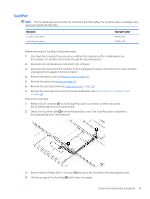
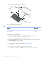
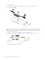
2. Remove the three Phillips M2.0×3.2 screws that secure the system board to the keyboard/top cover. 3. Lift the front edge of the system board (1) until it rests at an angle. 4. Slide the system board (2) forward until the rear edge of the system board is clear of the keyboard/ top cover. 5. Swing the front edge of the system board (1) up and back until the system board rests upside down on the keyboard/top cover. 6. Remove the Phillips M2.0×1.8 screw (2) that secures the WLAN module bracket to the system board. 7. Remove the WLAN module bracket (3). The WLAN module bracket is available using spare part number L07401-001. 44 Chapter 5 Removal and replacement procedures
-
 1
1 -
2
-
3
-
4
-
5
-
6
-
7
-
8
-
9
-
10
-
11
-
12
-
13
-
14
-
15
-
16
-
17
-
18
-
19
-
20
-
21
-
22
-
23
-
24
-
25
-
26
-
27
-
28
-
29
-
30
-
31
-
32
-
33
-
34
-
35
-
36
-
37
-
38
-
39
-
40
-
41
-
42
-
43
-
44
-
45
-
46
-
 47
47 -
 48
48 -
 49
49 -
 50
50 -
 51
51 -
 52
52 -
 53
53 -
 54
54 -
 55
55 -
 56
56 -
 57
57 -
58
-
59
-
60
-
61
-
62
-
63
-
64
-
65
-
66
-
67
-
68
-
69
-
70
-
71
-
72
-
73
-
74
-
75
-
76
-
77
 |
 |

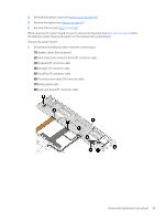
2.
Remove the three Phillips M2.0×3.2 screws that secure the system board to the keyboard/top cover.
3.
Lift the front edge of the system board
(1)
until it rests at an angle.
4.
Slide the system board
(2)
forward until the rear edge of the system board is clear of the keyboard/
top cover.
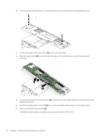
5.
Swing the front edge of the system board
(1)
up and back until the system board rests upside down on the
keyboard/top cover.
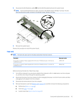
6.
Remove the Phillips M2.0×1.8 screw
(2)
that secures the WLAN module bracket to the system board.
7.
Remove the WLAN module bracket
(3)
.
The WLAN module bracket is available using spare part number L07401-001.
44
Chapter 5
Removal and replacement procedures