HP Spectre 13-af000 Maintenance and Service Guide - Page 44
Solid-state drive connector board, Remove the two Phillips M2.0×1.8 screws
 |
View all HP Spectre 13-af000 manuals
Add to My Manuals
Save this manual to your list of manuals |
Page 44 highlights
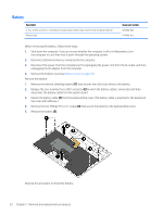
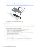
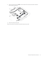
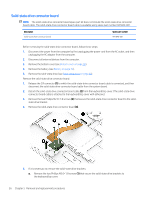
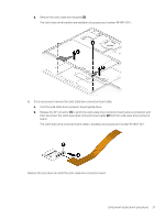
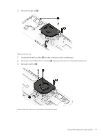
Solid-state drive connector board NOTE: The solid-state drive connector board spare part kit does not include the solid-state drive connector board cable. The solid-state drive connector board cable is available using spare part number 941842-001. Description Solid-state drive connector board Spare part number 941840-001 Before removing the solid-state drive connector board, follow these steps: 1. Disconnect the power from the computer by first unplugging the power cord from the AC outlet, and then unplugging the AC adapter from the computer. 2. Disconnect all external devices from the computer. 3. Remove the bottom cover (see Bottom cover on page 30). 4. Remove the battery (see Battery on page 32). 5. Remove the solid-state drive (see Solid-state drive on page 33). Remove the solid-state drive connector board: 1. Release the ZIF connector (1) to which the solid-state drive connector board cable is connected, and then disconnect the solid-state drive connector board cable from the system board. 2. Detach the solid-state drive connector board cable (2) from the keyboard/top cover. (The solid-state drive connector board cable is attached to the keyboard/top cover with adhesive.) 3. Remove the two Phillips M2.0×1.8 screws (3) that secure the solid-state drive connector board to the solidstate drive bracket. 4. Remove the solid-state drive connector board (4). 5. If it is necessary to remove the solid-state drive brackets: a. Remove the two Phillips M2.0×1.8 screws (1) that secure the solid-state drive brackets to the keyboard/top cover. 36 Chapter 5 Removal and replacement procedures
-
 1
1 -
2
-
3
-
4
-
5
-
6
-
7
-
8
-
9
-
10
-
11
-
12
-
13
-
14
-
15
-
16
-
17
-
18
-
19
-
20
-
21
-
22
-
23
-
24
-
25
-
26
-
27
-
28
-
29
-
30
-
31
-
32
-
33
-
34
-
35
-
36
-
37
-
38
-
 39
39 -
 40
40 -
 41
41 -
 42
42 -
 43
43 -
 44
44 -
 45
45 -
 46
46 -
 47
47 -
 48
48 -
 49
49 -
50
-
51
-
52
-
53
-
54
-
55
-
56
-
57
-
58
-
59
-
60
-
61
-
62
-
63
-
64
-
65
-
66
-
67
-
68
-
69
-
70
-
71
-
72
-
73
-
74
-
75
-
76
-
77
 |
 |