HP Stream x360 Maintenance and Service Guide - Page 49
Power connector cable, as far as it will open.
 |
View all HP Stream x360 manuals
Add to My Manuals
Save this manual to your list of manuals |
Page 49 highlights
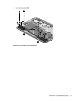
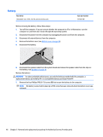
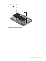
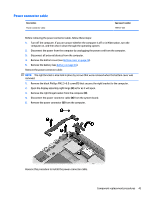
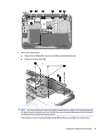
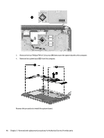
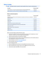
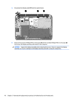
Power connector cable Description Power connector cable Spare part number 755727-001 Before removing the power connector cable, follow these steps: 1. Turn off the computer. If you are unsure whether the computer is off or in Hibernation, turn the computer on, and then shut it down through the operating system. 2. Disconnect the power from the computer by unplugging the power cord from the computer. 3. Disconnect all external devices from the computer. 4. Remove the bottom cover (see Bottom cover on page 28). 5. Remove the battery (see Battery on page 40). Remove the power connector cable: NOTE: The right bracket is also held in place by screws that were removed when the bottom cover was removed. 1. Remove the black Phillips PM2.5×6.0 screw (1) that secures the right bracket to the computer. 2. Open the display assembly right hinge (2) as far as it will open. 3. Remove the right hinge bracket from the computer (3). 4. Disconnect the power connector cable (4) from the system board. 5. Remove the power connector (5) from the computer. Reverse this procedure to install the power connector cable. Component replacement procedures 43
-
 1
1 -
2
-
3
-
4
-
5
-
6
-
7
-
8
-
9
-
10
-
11
-
12
-
13
-
14
-
15
-
16
-
17
-
18
-
19
-
20
-
21
-
22
-
23
-
24
-
25
-
26
-
27
-
28
-
29
-
30
-
31
-
32
-
33
-
34
-
35
-
36
-
37
-
38
-
39
-
40
-
41
-
42
-
43
-
 44
44 -
 45
45 -
 46
46 -
 47
47 -
 48
48 -
 49
49 -
 50
50 -
 51
51 -
 52
52 -
 53
53 -
 54
54 -
55
-
56
-
57
-
58
-
59
-
60
-
61
-
62
-
63
-
64
-
65
-
66
-
67
-
68
-
69
-
70
-
71
-
72
-
73
 |
 |
