HP Stream x360 Maintenance and Service Guide - Page 53
Display assembly, Display assembly subcomponents
 |
View all HP Stream x360 manuals
Add to My Manuals
Save this manual to your list of manuals |
Page 53 highlights
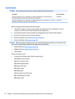
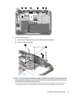
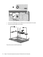
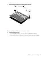
Display assembly NOTE: The display assembly is spared as a whole assembly and also is spared as subcomponents. Description Display assembly (11.6 in [29.5 cm], AG, SVA, LED TouchScreen) with WLAN and WWAN support Display assembly (11.6 in [29.5 cm], AG, SVA, LED TouchScreen) with WLAN support Spare part number 794293-001 794294-001 Display assembly subcomponents Description Spare part number Display bezel, for use with the raw panel (includes bezel, touch glass, touch control board, and magnets for 794290-001 hibernation and 360) Display cable 761350-001 Display enclosure 794287-001 Display hinge 794308-001 Display hinge covers (includes top and bottom covers) 794292-001 Display raw panel (includes display screw mylar covers and rubber gaskets) 794295-001 Proximity sensor board 788218-001 Webcam (includes microphone rubber gaskets) 794303-001 WLAN antenna 794285-001 WWAN dual antenna 794286-001 Before removing the display assembly, follow these steps: 1. Shut down the computer. If you are unsure whether the computer is off or in Hibernation, turn the computer on, and then shut it down through the operating system. 2. Disconnect all external devices connected to the computer. 3. Disconnect the power from the computer by first unplugging the power cord from the AC outlet and then unplugging the AC adapter from the computer. 4. Remove the bottom cover (see Bottom cover on page 28). 5. Remove the battery (see Battery on page 40). To remove the display assembly: 1. Release the WWAN wireless antennas from the clips (1) built into the base enclosure. 2. Release the WLAN wireless antenna cable from the clip (2) built into the base enclosure. 3. Disconnect the webcam cable (3) from the system board. Component replacement procedures 47
-
 1
1 -
2
-
3
-
4
-
5
-
6
-
7
-
8
-
9
-
10
-
11
-
12
-
13
-
14
-
15
-
16
-
17
-
18
-
19
-
20
-
21
-
22
-
23
-
24
-
25
-
26
-
27
-
28
-
29
-
30
-
31
-
32
-
33
-
34
-
35
-
36
-
37
-
38
-
39
-
40
-
41
-
42
-
43
-
44
-
45
-
46
-
47
-
 48
48 -
 49
49 -
 50
50 -
 51
51 -
 52
52 -
 53
53 -
 54
54 -
 55
55 -
 56
56 -
 57
57 -
 58
58 -
59
-
60
-
61
-
62
-
63
-
64
-
65
-
66
-
67
-
68
-
69
-
70
-
71
-
72
-
73
 |
 |
