HP nx6125 HP Compaq nx6115 and nx6125 Notebook PC - Maintenance and Service Gu - Page 102
Disassembly Sequence Chart, Description - replacement batteries
 |
View all HP nx6125 manuals
Add to My Manuals
Save this manual to your list of manuals |
Page 102 highlights
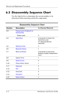
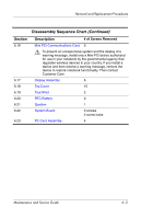
Removal and Replacement Procedures 6.2 Disassembly Sequence Chart Use the chart below to determine the section number to be referenced when removing notebook components. Section 6.3 6.4 6.5 6.6 6.7 6.8 6.9 6.10 6.11 6.12 6.13 6.14 6.15 Disassembly Sequence Chart Description Preparing the Notebook for Disassembly Battery pack Hard Drive Notebook Feet Bluetooth Board Memory Module Optical Drive Switch Cover Power Button Board Keyboard Fan Heat Sink Processor Button Board # of Screws Removed 0 2 loosened to remove the hard drive cover 4 to disassemble the hard drive 0 1 2 loosened to remove the memory module compartment cover 1 4 1 4 3 4 0 1 6-2 Maintenance and Service Guide
-
 1
1 -
2
-
3
-
4
-
5
-
6
-
7
-
8
-
9
-
10
-
11
-
12
-
13
-
14
-
15
-
16
-
17
-
18
-
19
-
20
-
21
-
22
-
23
-
24
-
25
-
26
-
27
-
28
-
29
-
30
-
31
-
32
-
33
-
34
-
35
-
36
-
37
-
38
-
39
-
40
-
41
-
42
-
43
-
44
-
45
-
46
-
47
-
48
-
49
-
50
-
51
-
52
-
53
-
54
-
55
-
56
-
57
-
58
-
59
-
60
-
61
-
62
-
63
-
64
-
65
-
66
-
67
-
68
-
69
-
70
-
71
-
72
-
73
-
74
-
75
-
76
-
77
-
78
-
79
-
80
-
81
-
82
-
83
-
84
-
85
-
86
-
87
-
88
-
89
-
90
-
91
-
92
-
93
-
94
-
95
-
96
-
 97
97 -
 98
98 -
 99
99 -
 100
100 -
 101
101 -
 102
102 -
 103
103 -
 104
104 -
 105
105 -
 106
106 -
 107
107 -
108
-
109
-
110
-
111
-
112
-
113
-
114
-
115
-
116
-
117
-
118
-
119
-
120
-
121
-
122
-
123
-
124
-
125
-
126
-
127
-
128
-
129
-
130
-
131
-
132
-
133
-
134
-
135
-
136
-
137
-
138
-
139
-
140
-
141
-
142
-
143
-
144
-
145
-
146
-
147
-
148
-
149
-
150
-
151
-
152
-
153
-
154
-
155
-
156
-
157
-
158
-
159
-
160
-
161
-
162
-
163
-
164
-
165
-
166
-
167
-
168
-
169
-
170
-
171
-
172
-
173
-
174
-
175
-
176
-
177
-
178
-
179
-
180
-
181
-
182
-
183
-
184
-
185
-
186
-
187
-
188
-
189
-
190
-
191
-
192
-
193
-
194
-
195
-
196
-
197
-
198
-
199
-
200
-
201
-
202
-
203
-
204
-
205
-
206
-
207
-
208
-
209
-
210
-
211
-
212
-
213
-
214
-
215
-
216
-
217
-
218
-
219
-
220
-
221
-
222
-
223
-
224
 |
 |
6–2
Maintenance and Service Guide
Removal and Replacement Procedures
6.2
Disassembly Sequence Chart
Use the chart below to determine the section number to be
referenced when removing notebook components.
Disassembly Sequence Chart
Section
Description
# of Screws Removed
6.3
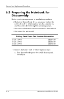
Preparing the Notebook for
Disassembly
Battery pack
0
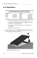
6.4
Hard Drive
2 loosened to remove the
hard drive cover
4 to disassemble the
hard drive
6.5
Notebook Feet
0
6.6
Bluetooth Board
1
6.7
Memory Module
2 loosened to remove the
memory module compartment
cover
6.8
Optical Drive
1
6.9
Switch Cover
4
6.10
Power Button Board
1
6.11
Keyboard
4
6.12
Fan
3
6.13
Heat Sink
4
6.14
Processor
0
6.15
Button Board
1