HP nx6125 HP Compaq nx6115 and nx6125 Notebook PC - Maintenance and Service Gu - Page 152
base enclosure., Slide the system board to the right
 |
View all HP nx6125 manuals
Add to My Manuals
Save this manual to your list of manuals |
Page 152 highlights
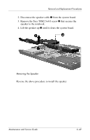
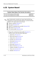
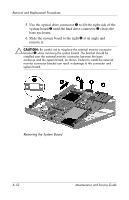
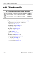
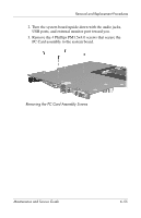
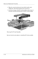
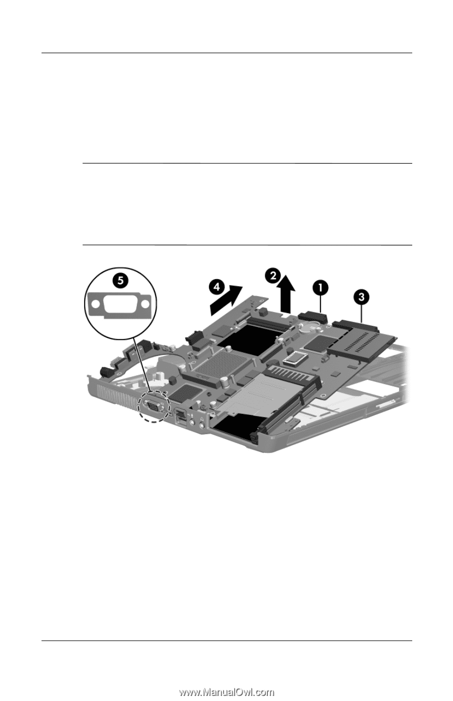
Removal and Replacement Procedures 5. Use the optical drive connector 1 to lift the right side of the system board 2 until the hard drive connector 3 clears the base enclosure. 6. Slide the system board to the right 4 at an angle and remove it. Ä CAUTION: Be careful not to misplace the external monitor connector bracket 5 when removing the system board. The bracket should be installed over the external monitor connector between the base enclosure and the system board, as shown. Failure to install the external monitor connector bracket can result in damage to the connector and system board. Removing the System Board 6-52 Maintenance and Service Guide
-
 1
1 -
2
-
3
-
4
-
5
-
6
-
7
-
8
-
9
-
10
-
11
-
12
-
13
-
14
-
15
-
16
-
17
-
18
-
19
-
20
-
21
-
22
-
23
-
24
-
25
-
26
-
27
-
28
-
29
-
30
-
31
-
32
-
33
-
34
-
35
-
36
-
37
-
38
-
39
-
40
-
41
-
42
-
43
-
44
-
45
-
46
-
47
-
48
-
49
-
50
-
51
-
52
-
53
-
54
-
55
-
56
-
57
-
58
-
59
-
60
-
61
-
62
-
63
-
64
-
65
-
66
-
67
-
68
-
69
-
70
-
71
-
72
-
73
-
74
-
75
-
76
-
77
-
78
-
79
-
80
-
81
-
82
-
83
-
84
-
85
-
86
-
87
-
88
-
89
-
90
-
91
-
92
-
93
-
94
-
95
-
96
-
97
-
98
-
99
-
100
-
101
-
102
-
103
-
104
-
105
-
106
-
107
-
108
-
109
-
110
-
111
-
112
-
113
-
114
-
115
-
116
-
117
-
118
-
119
-
120
-
121
-
122
-
123
-
124
-
125
-
126
-
127
-
128
-
129
-
130
-
131
-
132
-
133
-
134
-
135
-
136
-
137
-
138
-
139
-
140
-
141
-
142
-
143
-
144
-
145
-
146
-
 147
147 -
 148
148 -
 149
149 -
 150
150 -
 151
151 -
 152
152 -
 153
153 -
 154
154 -
 155
155 -
 156
156 -
 157
157 -
158
-
159
-
160
-
161
-
162
-
163
-
164
-
165
-
166
-
167
-
168
-
169
-
170
-
171
-
172
-
173
-
174
-
175
-
176
-
177
-
178
-
179
-
180
-
181
-
182
-
183
-
184
-
185
-
186
-
187
-
188
-
189
-
190
-
191
-
192
-
193
-
194
-
195
-
196
-
197
-
198
-
199
-
200
-
201
-
202
-
203
-
204
-
205
-
206
-
207
-
208
-
209
-
210
-
211
-
212
-
213
-
214
-
215
-
216
-
217
-
218
-
219
-
220
-
221
-
222
-
223
-
224
 |
 |
6–52
Maintenance and Service Guide
Removal and Replacement Procedures
5. Use the optical drive connector
1
to lift the right side of the
system board
2
until the hard drive connector
3
clears the
base enclosure.
6. Slide the system board to the right
4
at an angle and
remove it.
Ä
CAUTION:
Be careful not to misplace the external monitor connector
bracket
5
when removing the system board. The bracket should be
installed over the external monitor connector between the base
enclosure and the system board, as shown. Failure to install the external
monitor connector bracket can result in damage to the connector and
system board.
Removing the System Board