HP nx6125 HP Compaq nx6115 and nx6125 Notebook PC - Maintenance and Service Gu - Page 113
Memory modules are slotted, to prevent incorrect installation
 |
View all HP nx6125 manuals
Add to My Manuals
Save this manual to your list of manuals |
Page 113 highlights
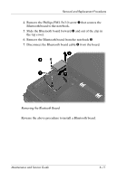
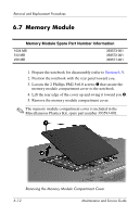
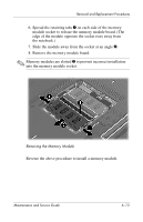
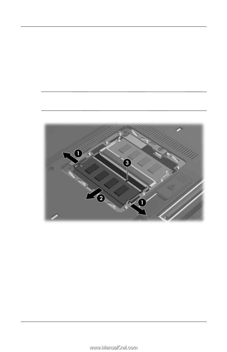
Removal and Replacement Procedures 6. Spread the retaining tabs 1 on each side of the memory module socket to release the memory module board. (The edge of the module opposite the socket rises away from the notebook.) 7. Slide the module away from the socket at an angle 2. 8. Remove the memory module board. ✎ Memory modules are slotted 3 to prevent incorrect installation into the memory module socket. Removing the Memory Module Reverse the above procedure to install a memory module. Maintenance and Service Guide 6-13
-
 1
1 -
2
-
3
-
4
-
5
-
6
-
7
-
8
-
9
-
10
-
11
-
12
-
13
-
14
-
15
-
16
-
17
-
18
-
19
-
20
-
21
-
22
-
23
-
24
-
25
-
26
-
27
-
28
-
29
-
30
-
31
-
32
-
33
-
34
-
35
-
36
-
37
-
38
-
39
-
40
-
41
-
42
-
43
-
44
-
45
-
46
-
47
-
48
-
49
-
50
-
51
-
52
-
53
-
54
-
55
-
56
-
57
-
58
-
59
-
60
-
61
-
62
-
63
-
64
-
65
-
66
-
67
-
68
-
69
-
70
-
71
-
72
-
73
-
74
-
75
-
76
-
77
-
78
-
79
-
80
-
81
-
82
-
83
-
84
-
85
-
86
-
87
-
88
-
89
-
90
-
91
-
92
-
93
-
94
-
95
-
96
-
97
-
98
-
99
-
100
-
101
-
102
-
103
-
104
-
105
-
106
-
107
-
 108
108 -
 109
109 -
 110
110 -
 111
111 -
 112
112 -
 113
113 -
 114
114 -
 115
115 -
 116
116 -
 117
117 -
 118
118 -
119
-
120
-
121
-
122
-
123
-
124
-
125
-
126
-
127
-
128
-
129
-
130
-
131
-
132
-
133
-
134
-
135
-
136
-
137
-
138
-
139
-
140
-
141
-
142
-
143
-
144
-
145
-
146
-
147
-
148
-
149
-
150
-
151
-
152
-
153
-
154
-
155
-
156
-
157
-
158
-
159
-
160
-
161
-
162
-
163
-
164
-
165
-
166
-
167
-
168
-
169
-
170
-
171
-
172
-
173
-
174
-
175
-
176
-
177
-
178
-
179
-
180
-
181
-
182
-
183
-
184
-
185
-
186
-
187
-
188
-
189
-
190
-
191
-
192
-
193
-
194
-
195
-
196
-
197
-
198
-
199
-
200
-
201
-
202
-
203
-
204
-
205
-
206
-
207
-
208
-
209
-
210
-
211
-
212
-
213
-
214
-
215
-
216
-
217
-
218
-
219
-
220
-
221
-
222
-
223
-
224
 |
 |
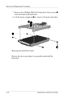
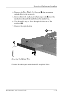
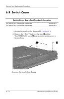
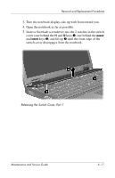
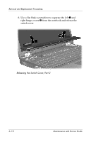
Removal and Replacement Procedures
Maintenance and Service Guide
6–13
6. Spread the retaining tabs
1
on each side of the memory
module socket to release the memory module board. (The
edge of the module opposite the socket rises away from
the notebook.)
7. Slide the module away from the socket at an angle
2
.
8. Remove the memory module board.
✎
Memory modules are slotted
3
to prevent incorrect installation
into the memory module socket.
Removing the Memory Module
Reverse the above procedure to install a memory module.