HP nx6125 HP Compaq nx6115 and nx6125 Notebook PC - Maintenance and Service Gu - Page 135
card away from the socket at a 45-degree angle, Remove the Mini PCI communications card by pulling
 |
View all HP nx6125 manuals
Add to My Manuals
Save this manual to your list of manuals |
Page 135 highlights
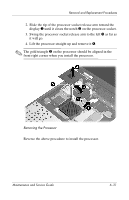
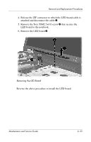
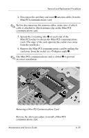
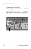
Removal and Replacement Procedures 4. Disconnect the auxiliary and main 1 antenna cables from the Mini PCI communications card. ✎ Before disconnecting the antenna cables, make note of which cable is attached to which antenna clip on the Mini PCI communications card. 5. Spread the 2 retaining tabs 2 on each side of the Mini PCI socket to release the Mini PCI communications card. (The edge of the card opposite the socket rises away from the notebook.) 6. Remove the Mini PCI communications card by pulling the card away from the socket at a 45-degree angle 3. ✎ The Mini PCI communications card is slotted 4 to prevent incorrect installation. Removing a Mini PCI Communications Card Reverse the above procedure to install a Mini PCI communications card. Maintenance and Service Guide 6-35
-
 1
1 -
2
-
3
-
4
-
5
-
6
-
7
-
8
-
9
-
10
-
11
-
12
-
13
-
14
-
15
-
16
-
17
-
18
-
19
-
20
-
21
-
22
-
23
-
24
-
25
-
26
-
27
-
28
-
29
-
30
-
31
-
32
-
33
-
34
-
35
-
36
-
37
-
38
-
39
-
40
-
41
-
42
-
43
-
44
-
45
-
46
-
47
-
48
-
49
-
50
-
51
-
52
-
53
-
54
-
55
-
56
-
57
-
58
-
59
-
60
-
61
-
62
-
63
-
64
-
65
-
66
-
67
-
68
-
69
-
70
-
71
-
72
-
73
-
74
-
75
-
76
-
77
-
78
-
79
-
80
-
81
-
82
-
83
-
84
-
85
-
86
-
87
-
88
-
89
-
90
-
91
-
92
-
93
-
94
-
95
-
96
-
97
-
98
-
99
-
100
-
101
-
102
-
103
-
104
-
105
-
106
-
107
-
108
-
109
-
110
-
111
-
112
-
113
-
114
-
115
-
116
-
117
-
118
-
119
-
120
-
121
-
122
-
123
-
124
-
125
-
126
-
127
-
128
-
129
-
 130
130 -
 131
131 -
 132
132 -
 133
133 -
 134
134 -
 135
135 -
 136
136 -
 137
137 -
 138
138 -
 139
139 -
 140
140 -
141
-
142
-
143
-
144
-
145
-
146
-
147
-
148
-
149
-
150
-
151
-
152
-
153
-
154
-
155
-
156
-
157
-
158
-
159
-
160
-
161
-
162
-
163
-
164
-
165
-
166
-
167
-
168
-
169
-
170
-
171
-
172
-
173
-
174
-
175
-
176
-
177
-
178
-
179
-
180
-
181
-
182
-
183
-
184
-
185
-
186
-
187
-
188
-
189
-
190
-
191
-
192
-
193
-
194
-
195
-
196
-
197
-
198
-
199
-
200
-
201
-
202
-
203
-
204
-
205
-
206
-
207
-
208
-
209
-
210
-
211
-
212
-
213
-
214
-
215
-
216
-
217
-
218
-
219
-
220
-
221
-
222
-
223
-
224
 |
 |