Hitachi 51F59 Owners Guide - Page 62
Disassembly/Assembly Instructions
 |
View all Hitachi 51F59 manuals
Add to My Manuals
Save this manual to your list of manuals |
Page 62 highlights
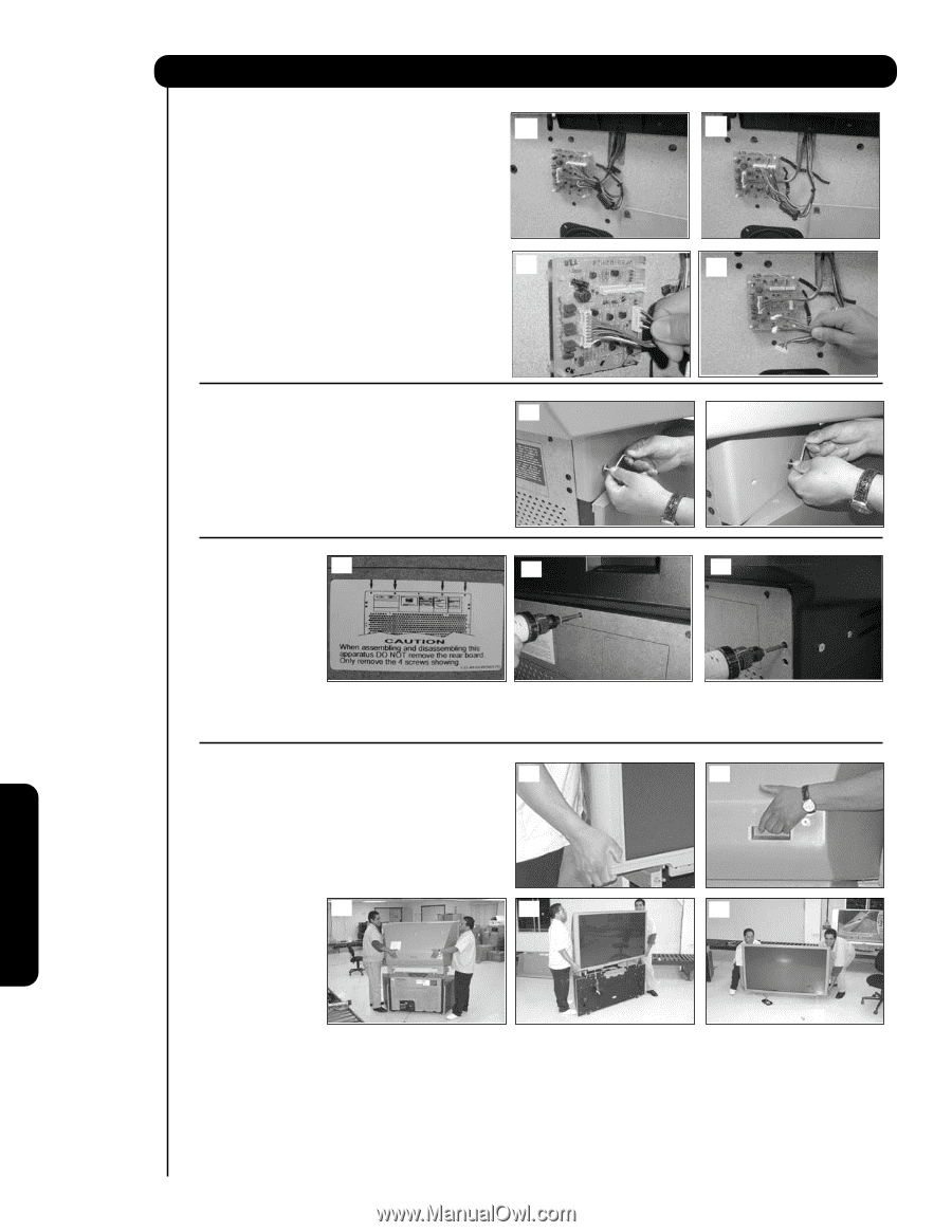
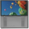
57" Disassembly/Assembly Instructions STEP 4 Locate the SENSOR PWB attaced to the cabinet (a) (b) (a). Losen the sensor wires from the plastic holders in order to remove the 3 wires that comes from the screen, see (b). Disconnect the 3 connector wires as it shows on picture (c) & (d). (c) (d) STEP 5 (a) (b) Remove the joint connector bolts from each side of the back cover using the allen wrench that is provided inside of the instruction bag, see (a) and (b). In case that the screw is different type use the proper screwdriver to remove the screws. STEP 6 (a) (b) (c) Remove from the back side of the TV set only the top 4 screws of the lower rear cover, see (b), as shown by the arrows on the rear cabinet label, see (a). Do not remove the rear cover board. Remove the (4) four side screws that hold the back cover to the cabinet, see (c) as shown on the label (a). Total of 8 screws will be removed. STEP 7 (a) (b) CAUTION: When the TV is separated, the top portion weights 45 lbs. This task should be done by two persons when separating this TV. This assembly contains fragile parts, such as glass and the viewing screen. Avoid any type of impact that could cause breakage of these components. Remove top portion by grabbing the (c) (d) (e) bottom corner of frame and the back cover, see (a)(b). Lift upwards, see (c)(d), gently place the top portion on the the floor, see (e). Useful Information 62
-
 1
1 -
2
-
3
-
4
-
5
-
6
-
7
-
8
-
9
-
10
-
11
-
12
-
13
-
14
-
15
-
16
-
17
-
18
-
19
-
20
-
21
-
22
-
23
-
24
-
25
-
26
-
27
-
28
-
29
-
30
-
31
-
32
-
33
-
34
-
35
-
36
-
37
-
38
-
39
-
40
-
41
-
42
-
43
-
44
-
45
-
46
-
47
-
48
-
49
-
50
-
51
-
52
-
53
-
54
-
55
-
56
-
 57
57 -
 58
58 -
 59
59 -
 60
60 -
 61
61 -
 62
62 -
 63
63 -
 64
64 -
 65
65 -
 66
66 -
 67
67 -
68
-
69
-
70
-
71
-
72
-
73
-
74
-
75
 |
 |