Hitachi CMP4221U Owners Guide - Page 36
PRODUCT PECIFICATIONS Continued, Signal Input
 |
View all Hitachi CMP4221U manuals
Add to My Manuals
Save this manual to your list of manuals |
Page 36 highlights
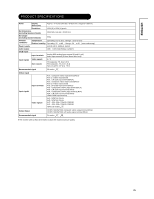
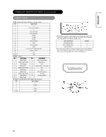
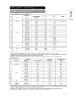
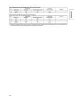
ENGLISH PRODUCT PECIFICATIONS (Continued) Signal Input RGB Input (D-sub 15-pin connector) Pin Input signal 1 R 2 G or sync on green 3 B 4 No connection 5 No connection 6 R.GND 7 G.GND 8 B.GND 9 No connection 10 GND 11 No connection 12 SDA 13 H. sync or H/V composite sync 14 V.sync. V.CLK 15 SCL Frame GND HDMI Input Pin Input signal Pin Input signal 1 TMDS Data2 11 TMDS Clock Shield 2 TMDS Data2 Shield 12 TMDS Clock- 3 TMDS Data2- 13 CEC 4 TMDS Data 1 14 Reserved(N.C. on device) 5 TMDS Data1 Shield 15 SCL 6 TMDS Data1- 16 SDA 7 TMDS Data0 17 DDC/CED Ground 8 TMDS Data0 Shield 18 5V Power 9 TMDS Data0- 19 Hot Plug Detect 10 TMDS Clock S-input connector pin specifications Pin Input signal 1 Y 2 Y-GND 3 C 4 C-GND Frame GND x When different kinds of input signals are simultaneously input to the monitor via a graphics board or the like, the monitor will automatically select the signals in the following priority order: Sync signal type Priority H/V separate sync. 1 H/V composite sync. 2 sync.on Green * 3 *Even in the case of the recommended signals shown on the following page, there may be instances when correct display is not possible. In this case, use H/V separate sync, or H/V composite sync. 36
-
 1
1 -
2
-
3
-
4
-
5
-
6
-
7
-
8
-
9
-
10
-
11
-
12
-
13
-
14
-
15
-
16
-
17
-
18
-
19
-
20
-
21
-
22
-
23
-
24
-
25
-
26
-
27
-
28
-
29
-
30
-
 31
31 -
 32
32 -
 33
33 -
 34
34 -
 35
35 -
 36
36 -
 37
37 -
 38
38
 |
 |
