Honeywell MK7580-30B41-00 User Guide
Honeywell MK7580-30B41-00 - Metrologic MS7580 Genesis Manual
 |
View all Honeywell MK7580-30B41-00 manuals
Add to My Manuals
Save this manual to your list of manuals |
Honeywell MK7580-30B41-00 manual content summary:
- Honeywell MK7580-30B41-00 | User Guide - Page 1
Genesis™ 7580 Presentation Area Imager User's Guide - Honeywell MK7580-30B41-00 | User Guide - Page 2
damages resulting from the furnishing, performance, or use of this manual. This document contains propriety information that is protected by copyright , Metrologic, MetroSet2, and TotalFreedom are trademarks or registered trademarks of Metrologic Instruments, Inc. or Honeywell International - Honeywell MK7580-30B41-00 | User Guide - Page 3
Maintenance...5 Cable Installation and Removal 6 Interface Installation RS232 ...7 Keyboard Wedge 8 RS485 ...9 USB ...10 Mounting the MS7580 Components of Adapter Kit 46-00911 13 Components of Wall Mount Kit 46-00913 13 Installation of Adapter Kit 46-00911 14 Installation of Wall Mount Kit 46 - Honeywell MK7580-30B41-00 | User Guide - Page 4
Imager Pinouts-MS7580-124-EAS 46 Cable Pinouts 47 Antenna Disconnect 47 Imager and Cable Terminations Standard Imager Pinouts 49 Standard Cable Pinouts 50 Limited Warranty 53 Regulatory Compliance Safety ...55 EMC ...56 Index ...59 Customer Support 61 Technical Assistance 61 Product Service - Honeywell MK7580-30B41-00 | User Guide - Page 5
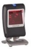
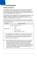
sensor (IR) that instantly turns on the imager when an object is presented within the imager's field of view. Genesis™ Interface Support Interfaces supported include: MS7580-124 • RS232 • USB • Keyboard Wedge • RS485 (External via Cable) EAS equipped models are indicated with an - Honeywell MK7580-30B41-00 | User Guide - Page 6
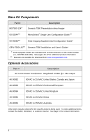
Base Kit Components Part # MS7580-124 Description Genesis 7580 Presentation Area Imager 00-02544 MetroSelect® Single-Line Configuration Guide 00-05252 Area-Imaging Supplemental Configuration Guide* GEN-7580-UG Genesis 7580 Installation and User's Guide* EAS equipped models are - Honeywell MK7580-30B41-00 | User Guide - Page 7
12V VLink Straight, Black Cable with Built in Power Jack MX-5S236-E-3 USB 12V VLink Straight Black Cable with Built in Power Jack, Non-Locking Type A Connector 46-00911 46-00913 00-05250 MS7580 Wall Mount Adapter Kit MS7580 Wall Mount Kit MS7580 Wall Mount Installation Guide Other items may be - Honeywell MK7580-30B41-00 | User Guide - Page 8
10-pin RJ45, Female Socket, See Imager Pinout Connections (on page 49) 7 Cable Release See Cable Installation and Removal (on page 6) Note: The MS7580-124-EAS model is equipped with an integrated antenna for Electronic Article Surveillance (EAS) system support. See pages 39-47 for additional - Honeywell MK7580-30B41-00 | User Guide - Page 9
MS7580 has a label located near the top of the output window. This label provides the imager's model number, date of manufacture, serial number, CE and caution information. Additional information has been molded into the underside of the imager connected to the scanner must meet the requirements - Honeywell MK7580-30B41-00 | User Guide - Page 10
lock. 4. Pull gently on the strain-relief of the cable to remove the cable from the imager. Figure 4. Disconnecting the Cable MS7580-124-EAS Model Note See page 39 for additional cable installation/removal instructions specific to the MS7580-124-EAS Genesis with integrated RF EAS antenna. 6 - Honeywell MK7580-30B41-00 | User Guide - Page 11
-Line Configuration Guide (PN 00-02544) or MetroSet2's help files for instructions on changing the imager's configuration. In addition, please check that the imager and host system are using the same communication protocol. The MS7580 requires 12V power to function for RS232 operation. Honeywell - Honeywell MK7580-30B41-00 | User Guide - Page 12
settings. Please refer to the MetroSelect Single-Line Configuration Guide (PN 00-02544) or MetroSet2's help files for instructions on changing the imager's configuration. In addition, please check that the imager and host system are using the same communication protocol. The MS7580 requires - Honeywell MK7580-30B41-00 | User Guide - Page 13
settings. Please refer to the MetroSelect Single-Line Configuration Guide (PN 00-02544) or MetroSet2's help files for instructions on changing the imager's configuration. In addition, please check that the imager and host system are using the same communication protocol. The MS7580 requires - Honeywell MK7580-30B41-00 | User Guide - Page 14
for additional installation instructions for MS7580124-EAS models. • The MS7580 meets the requirements for Full Speed USB hardware. The USB interface is configurable for Keyboard Emulation Mode, Bi-Directional Serial Emulation Mode or IBM OEM. The default setting for the USB interface is Keyboard - Honeywell MK7580-30B41-00 | User Guide - Page 15
properly to the host device. The imager is shipped from the factory configured with default settings. Please refer to the MetroSelect Single-Line Configuration Guide (PN 00-02544) or MetroSet2's help files for instructions on changing the imager's configuration. In addition, please check that the - Honeywell MK7580-30B41-00 | User Guide - Page 16
12 - Honeywell MK7580-30B41-00 | User Guide - Page 17
FHP Wood Screw G MS7580 Wall Mount Installation Guide Figure 9. 46-00911 Kit Components Qty. 1 1 1 4 4 3 1 Components of Wall Mount Kit 46-00913 Item Item Description A Wall Mount B #7 x 1.00 in. FHP Wood Screw C MS7580 Wall Mount Installation Guide Figure 10. 46-00913 Kit Components Qty - Honeywell MK7580-30B41-00 | User Guide - Page 18
bottom of the MS7580. 2. Attach the adapter plate to the bottom of the imager with the four M3 x .5 x 10 mm screws ( ) provided in the kit. 3. Attach the base plate to the adapter plate with the four M3 x .5 x 8 mm screws ( ) provided in the kit. Figure 11 4. Before mounting the locking plate - Honeywell MK7580-30B41-00 | User Guide - Page 19
5. Use the locking plate as a guide to drill three #39 pilot holes (A) in the mounting surface. Figure 13. Locking Plate (Not Drawn to Scale) 6. Secure the locking plate to the wall with the three #7 wood screws () provided in the kit. Figure 14 7. Position the imager so the base plate sits flush - Honeywell MK7580-30B41-00 | User Guide - Page 20
over the pilot holes with the arrow pointing up. 3. Secure the wall mount to the wall with the two #7 wood screws () provided in the kit. Figure 16 4. Slide the imager's base under the upper corner tabs on the wall mount. 5. Slide the remainder of the base in and down behind the lower corner tabs - Honeywell MK7580-30B41-00 | User Guide - Page 21
MS7580 supports two standard modes of operation for scanning bar codes, automatic activation and manual activation scanning. Scanning while in the automatic activation mode can occur in either one of two configurable options, pass-through or presentation . Presentation Scanning-The imager decodes - Honeywell MK7580-30B41-00 | User Guide - Page 22
will return to the default presentation mode by either the default time length or by double pressing the button. Note: Decoding and functional capability of the imager is restricted through the use of license numbers provided by Honeywell. Imagers will not support key features such as, but not - Honeywell MK7580-30B41-00 | User Guide - Page 23
The MS7580 provides audible feedback during operation. The audible feedback indicates the status of the imager. Eight settings are available for the tone of the beep (normal, 6 alternate tones and no tone). To change the tone, refer to the MetroSelect Single-Line Configuration Guide, PN 00-02544 - Honeywell MK7580-30B41-00 | User Guide - Page 24
is in stand-by mode. Present a bar code to the imager and the blue LED will switch to a high intensity blue when the IR detects the object. Steady High Intensity Blue The high intensity blue LED is illuminated when the imager is active and attempting to decode a barcode. Single White Flash When - Honeywell MK7580-30B41-00 | User Guide - Page 25
Failure Modes Long Razzberry Tone - During Power Up Failed to initialize or configure the imager. If the imager does not respond after reconfiguration, return the imager for repair. Short Razzberry Tone - During Scanning An Invalid bar code has been scanned when in configuration mode. 21 - Honeywell MK7580-30B41-00 | User Guide - Page 26
Field of View Figure 20. Field of View 22 - Honeywell MK7580-30B41-00 | User Guide - Page 27
and functional capability is limited and imagers will not support key features including, but not Honeywell. If you wish to purchase a limited license for one or more of the key features not included in the standard imager, please specify at the time of sale or otherwise contact a customer service - Honeywell MK7580-30B41-00 | User Guide - Page 28
IR Activation Range The MS7580 has a built in object detection sensor that instantly turns on the imager when an object is presented within the imager's IR Activation Area, shown below. Figure 22. IR Activation Area 24 - Honeywell MK7580-30B41-00 | User Guide - Page 29
Illumination Source Figure 23. Illumination Source 25 - Honeywell MK7580-30B41-00 | User Guide - Page 30
IR Source Figure 24. IR Source 26 - Honeywell MK7580-30B41-00 | User Guide - Page 31
Targeting Source Figure 25. Targeting Source 27 - Honeywell MK7580-30B41-00 | User Guide - Page 32
28 - Honeywell MK7580-30B41-00 | User Guide - Page 33
Troubleshooting Guide The following troubleshooting guide is for reference purposes only. Contact a customer service representative or technical support representative to preserve the limited warranty terms. See page 61 for contact information. All Interfaces Symptoms Possible Causes Solution - Honeywell MK7580-30B41-00 | User Guide - Page 34
USB Interfaces. The imager scans a bar code, but locks up after the first scan and the white LED stays on. The imager is configured to support some form of host handshaking but is not receiving the signal. If the imager is setup to support ACK/NAK, RTS/CTS, or XON/XOFF, verify that the host cable - Honeywell MK7580-30B41-00 | User Guide - Page 35
a check digit/character/or border problem. Check if check digits are set properly. Check if the correct minimum symbol length is set. The imager scans the bar code but there is no data. The configuration is not set correctly. Make sure the imager is configured for the appropriate mode. The next - Honeywell MK7580-30B41-00 | User Guide - Page 36
some inter-character delay to the transmitted output by using the Configuration Guides (PN 00-02544 and 00-05252). The following item is only relevant for a USB interface. The USB host may not be active. No LEDs, beep or Illumination The MS7580 will not operate from hub/host power without host - Honeywell MK7580-30B41-00 | User Guide - Page 37
: PC Keyboard Wedge, RS232, USB, RS485 (external via cable) Print Contrast: 20% Minimum Reflectance Difference Number Characters Read: 4096 Bytes Maximum Beeper Operation: 7 tones or no beep Indicators (LED) Default Settings: High Intensity Blue The imager is active and attempting to scan - Honeywell MK7580-30B41-00 | User Guide - Page 38
10 pin modular RJ45 Electrical Input Voltage: +12 Volt Adapter Value 12VDC ± 0.25V +5 Volt USB Power Value 5VDC ± 0.25V Peak 2.0 W (Typical) 1.6 W (Typical) Power: 0% to 95% Relative Humidity, Non-Condensing Up to 100,000 Lux Designed to withstand 1.5 m (5 ft.) drops Sealed to - Honeywell MK7580-30B41-00 | User Guide - Page 39
Emulation Mode or IBM OEM. The default USB setting is Keyboard Emulation Mode. The MS7580 with a built-in PC Keyboard Wedge interface is designed for Keyboard emulation use only. Many RS232 configurable functions, available in other Honeywell imagers, are also available as keyboard wedge functions - Honeywell MK7580-30B41-00 | User Guide - Page 40
36 - Honeywell MK7580-30B41-00 | User Guide - Page 41
MS7580 can be configured by scanning the bar codes included in the MetroSelect Single-Line Configuration Guide or the Area-Imaging Supplemental Configuration Guide. The manuals are available for download at www.honeywellaidc.com. • MetroSet2 This user-friendly Windows®-based configuration program - Honeywell MK7580-30B41-00 | User Guide - Page 42
port on the host system. 2. Start the MetroSet2 software. 3. Click on the plus sign (+) next to POS Scanners to expand the supported imager list. 4. Choose the MS7580 Genesis from the list. 5. Click on the Configure Genesis/7580 Scanner button. 6. Choose Flash Utility from the options list - Honeywell MK7580-30B41-00 | User Guide - Page 43
integration of an MS7580-124-EAS Genesis. Integrated RF EAS Antenna Connection The following information is applicable for MS7580-124-EAS kits containing an RS232, MX-5S114-E-3 cable or a USB, MX-5S236-E-3 cable. Insert the cable's EAS connector into the antenna connector on the imager. There will - Honeywell MK7580-30B41-00 | User Guide - Page 44
configuration. Antenna and Interlock† Connection Cable (MX-5S236-E-3 or MX-5S114-E-3) Wire Color Solid Light Green Solid Black Wire Gauge Thin settings. * Caution Statements For North America: Caution: To maintain compliance with applicable standards, all circuits connected to the scanner - Honeywell MK7580-30B41-00 | User Guide - Page 45
the Checkpoint device, two switch banks set the deactivation antenna tuning. The recommended settings for the switch banks are shown below. See page 44 for tag deactivation guidelines. Switch Bank Settings SW1 SW2 Switches 1 - 6 OFF Switches 1 - 6 OFF Settings of 0pF to 47pF are recommended - Honeywell MK7580-30B41-00 | User Guide - Page 46
for EAS Applications EAS support is disabled by default in the MS7580-124-EAS series. To enable EAS support the imager must be configured for a system type and signal mode. Follow the configuration sequence below to configure the imager for EAS functionality. 1. Scan the system type bar - Honeywell MK7580-30B41-00 | User Guide - Page 47
only). The EAS timeout length specifies the maximum time that the area imager will leave the EAS interlock signal asserted following a successful scan. The EAS timeout setting has no effect in continuous mode. Note: If the area imager routinely fails to deactivate EAS tags, increase the value of the - Honeywell MK7580-30B41-00 | User Guide - Page 48
not enclose or rest the imager's base in close proximity to dense metal. The metal may interfere with the antenna decreasing the expected deactivation range. Tag Storage Precaution Do not store tags within 45.7 cm [18.0″] of the MS7580. Tags stored closer than 45.7 cm [18.0″] may be unintentionally - Honeywell MK7580-30B41-00 | User Guide - Page 49
Figure 28. Expected Tag Deactivation Area (Top View) 45 - Honeywell MK7580-30B41-00 | User Guide - Page 50
Imager Pinouts-MS7580-124-EAS Figure 29. MS7580-124-EAS, 10-Pin Female Modular Socket RS232 USB Pin 1 2 3 4 5 6 7 Pin 4 in Cable No Connect Tied to Pin 2 in Cable Reserved USB D+ +5VDC USB Power USB D+12V Power Shield Ground Signal/Power Ground Integrated RF EAS Antenna (MS7580-124-EAS Models - Honeywell MK7580-30B41-00 | User Guide - Page 51
1 PC +5V/V_USB 2 D- 3 D+ 4 Ground Figure 32. USB Type A, Non-Locking Antenna Disconnect 1. Press the release lock on the cable's EAS connector. 2. Pull the connector free.. Figure 33. Antenna Disconnect ‡ MS7580-124-EAS compatible cables. For standard MS7580 cable pinouts refer to page 50. 47 - Honeywell MK7580-30B41-00 | User Guide - Page 52
48 - Honeywell MK7580-30B41-00 | User Guide - Page 53
Imager and Cable Terminations Standard Imager Pinouts‡ Figure 34. Back/Connector View of the MS7580 RS232 USB requires 12V power for pass-through functionality. Signals on Pin 6 and 8 are TTL level RS232 output signals. ‡ See page 46 for pinout information specific to the MS7580-124-EAS Genesis - Honeywell MK7580-30B41-00 | User Guide - Page 54
Pinouts‡ (Host End) RS232, 12V VLink Cable 5S-5S000-3 Pin Function 1 Shield Ground 2 RS232 Transmit Output 7-8 No Connect 5S-5S235-N-3 5S-5S213-3 USB Type A Non-Locking USB Type A Locking Plus-Power ‡ See page 47 for pinout information specific to the MS7580-124-EAS Genesis model. 50 - Honeywell MK7580-30B41-00 | User Guide - Page 55
5 +5VDC Pin Function 1 PC Data 2 No Connect 3 Power Ground 4 +5VDC 5 PC Clock 6 No Connect 5-Pin DIN, Female 6-Pin DIN, Male Honeywell will supply an adapter cable with a 5-pin DIN male connector on one end and a 6-pin mini DIN female connector on the other. According to the termination - Honeywell MK7580-30B41-00 | User Guide - Page 56
52 - Honeywell MK7580-30B41-00 | User Guide - Page 57
Materials Authorization, which may be obtained by contacting HII. In the event that the product is returned to HII or its authorized service center within the Warranty Period and HII determines to its satisfaction that the product is defective due to defects in materials or workmanship, HII, at its - Honeywell MK7580-30B41-00 | User Guide - Page 58
. This includes but is not limited to: cables, power supplies, cradles, and docking stations. HII extends these warranties only to the first endusers of the products. These warranties are non-transferable. The duration of the limited warranty for the MS7580 is two (2) year(s). The accessories have - Honeywell MK7580-30B41-00 | User Guide - Page 59
may result in hazardous radiation exposure. Under no circumstances should the customer attempt to service the LED scanner. Never attempt to look at the LED beam, even if the scanner appears to be nonfunctional. Never open the scanner in an attempt to look into the device. Doing so could result in - Honeywell MK7580-30B41-00 | User Guide - Page 60
compliance could void the user's authority to operate the equipment. Class A Devices The following is applicable when the scanner cable is greater in length than 3 meters (9.8 feet) when fully extended: Les instructions ci-dessous s'appliquent aux cables de scanner dépassant 3 métres (9.8 pieds) de - Honeywell MK7580-30B41-00 | User Guide - Page 61
Cet appareil numérique de classe A est conforme à la norme canadienne NMB-003. European Standard Warning This is a class A product. In a domestic environment this product may cause radio interference in which case the user may be required to take adequate measures. Warnung! Dies ist eine Einrichtung - Honeywell MK7580-30B41-00 | User Guide - Page 62
user's authority to operate the equipment. Class B Devices The following is applicable when the scanner cable is less than 3 meters (9.8 feet) in length when fully extended: Les instructions ci-dessous s'appliquent aux cables de scanner ICES-003. Remarque Cet appareil numérique de classe B est - Honeywell MK7580-30B41-00 | User Guide - Page 63
44-45 RS485 3, 9, 44-45 Termination 4 USB 3, 10, 11, 44-45 VLink.. 2, 3, 7-11, 25-28, 34, 44- 45 Caution 7-11, 49 CE 5, 7-11 Code Type 17, 18, 23, 30 Compliance 7-11, 48, 49-52 Configuration ....... 25-28, 31, 33, 34 Connector Pinouts 43 Current 30 Customer Service 2, 3, 48 D DC 2, 30, 43 - Honeywell MK7580-30B41-00 | User Guide - Page 64
7-11 Service 48 Specifications Electrical 30 Environmental 30 Mechanical 30 Operational 29 Swiftdecoder 1 T Tone 20-21 Transformer 2, 7-11, 30 Troubleshooting 25-28 U UL 5, 7-11 Upgrade 34 V Ventilation 30 Visual Indicator 20-21, 34 Voltage 30 W Wall Mount 13-16 Warranty 48 White - Honeywell MK7580-30B41-00 | User Guide - Page 65
Technical Assistance If you need assistance installing or troubleshooting your device, please call your distributor or the nearest technical support office: North America/Canada Telephone: (800) 782-4263 E-mail: [email protected] Latin America Telephone: (803) 835-8000 Telephone: (800 - Honeywell MK7580-30B41-00 | User Guide - Page 66
Product Service and Repair Honeywell International Inc. provides service for all its products through service centers throughout the world. To obtain warranty or non-warranty service, contact the appropriate location below to obtain a Return Material Authorization number (RMA #) before returning the - Honeywell MK7580-30B41-00 | User Guide - Page 67
- Honeywell MK7580-30B41-00 | User Guide - Page 68
Honeywell Scanning & Mobility 9680 Old Bailes Road Fort Mill, SC 29707 www.honeywellaidc.com GEN-7580-UG Rev C 10/11
-
 1
1 -
 2
2 -
 3
3 -
 4
4 -
 5
5 -
 6
6 -
 7
7 -
8
-
9
-
10
-
11
-
12
-
13
-
14
-
15
-
16
-
17
-
18
-
19
-
20
-
21
-
22
-
23
-
24
-
25
-
26
-
27
-
28
-
29
-
30
-
31
-
32
-
33
-
34
-
35
-
36
-
37
-
38
-
39
-
40
-
41
-
42
-
43
-
44
-
45
-
46
-
47
-
48
-
49
-
50
-
51
-
52
-
53
-
54
-
55
-
56
-
57
-
58
-
59
-
60
-
61
-
62
-
63
-
64
-
65
-
66
-
67
-
68
 |
 |

Genesis
™
Presentation Area Imager
7580
User’s Guide