Honeywell MK7580-30B41-00 User Guide - Page 44
EAS System Connection, Checkpoint - gauges
 |
View all Honeywell MK7580-30B41-00 manuals
Add to My Manuals
Save this manual to your list of manuals |
Page 44 highlights
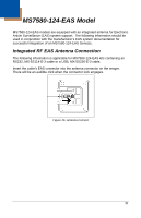
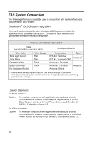
EAS System Connection The following information should be used in conjunction with the manufacturer's documentation EAS system. Checkpoint® EAS System Integration Honeywell cables compatible with Checkpoint EAS systems include five additional wires for device connection*. Consult the table below for the appropriate wire and terminal configuration. Antenna and Interlock† Connection Cable (MX-5S236-E-3 or MX-5S114-E-3) Wire Color Solid Light Green Solid Black Wire Gauge Thin Thin Red and White Black and White Thick Thick No Insulation/Shield Checkpoint Device Connection INTLK + Terminal INTLK - Terminal, GND Antenna + Terminal Antenna - Terminal Antenna Shield Type Interlock† Antenna † Interlock functionality requires specific EAS device settings. Consult the manufacturer's EAS system documentation for the appropriate switch and timing potentiometer settings. * Caution Statements For North America: Caution: To maintain compliance with applicable standards, all circuits connected to the scanner must meet the requirements of a NEC Class 2 power source or Limited Power Source as defined in UL 60950-1 2nd edition Clause 2.5. For Other Countries: Caution: To maintain compliance with applicable standards, all circuits connected to the scanner must meet the requirements of a Limited Power Source as defined in IEC 60950-1 2nd edition Clause 2.5. 40
-
 1
1 -
2
-
3
-
4
-
5
-
6
-
7
-
8
-
9
-
10
-
11
-
12
-
13
-
14
-
15
-
16
-
17
-
18
-
19
-
20
-
21
-
22
-
23
-
24
-
25
-
26
-
27
-
28
-
29
-
30
-
31
-
32
-
33
-
34
-
35
-
36
-
37
-
38
-
 39
39 -
 40
40 -
 41
41 -
 42
42 -
 43
43 -
 44
44 -
 45
45 -
 46
46 -
 47
47 -
 48
48 -
 49
49 -
50
-
51
-
52
-
53
-
54
-
55
-
56
-
57
-
58
-
59
-
60
-
61
-
62
-
63
-
64
-
65
-
66
-
67
-
68
 |
 |
