Honeywell MK7580-30B41-00 User Guide - Page 11
Interface Installation, RS232 - configuration
 |
View all Honeywell MK7580-30B41-00 manuals
Add to My Manuals
Save this manual to your list of manuals |
Page 11 highlights
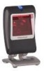
Interface Installation RS232 1. Turn off power to the host device. 2. Plug the interface cable's modular connector into the socket on the imager. 3. Connect the other end of the cable to a dedicated COM port on the host device. 4. Plug the 12V power supply into the power jack on the cable. 5. Check the AC input requirements of the power supply to verify the voltage matches the AC outlet. The outlet must be located near the equipment and easily accessible. 6. Connect AC power to the transformer. 7. The MS7580 will start to initialize. The white and blue LED will alternately fade on and off for three seconds. When the imager has finished initializing, the imager will flash the white LED three times while simultaneously beeping three times. The low intensity blue LED will remain turned on. 8. Turn on power to the host device. Figure 5. RS232 See caution on page 5. Installation Notes • MS7580-124-EAS models are equipped with an integrated RF EAS antenna. See page 39 for additional cable installation instructions for EAS equipped Genesis models. • Plugging the imager into a port on the host system does not guarantee that scanned information will be communicated properly to the host system. The imager is shipped from the factory configured with default settings. Please refer to the MetroSelect Single-Line Configuration Guide (PN 00-02544) or MetroSet2's help files for instructions on changing the imager's configuration. In addition, please check that the imager and host system are using the same communication protocol. The MS7580 requires 12V power to function for RS232 operation. Honeywell recommends using the external power supply shipped with the MS7580. 7
-
 1
1 -
2
-
3
-
4
-
5
-
 6
6 -
 7
7 -
 8
8 -
 9
9 -
 10
10 -
 11
11 -
 12
12 -
 13
13 -
 14
14 -
 15
15 -
 16
16 -
17
-
18
-
19
-
20
-
21
-
22
-
23
-
24
-
25
-
26
-
27
-
28
-
29
-
30
-
31
-
32
-
33
-
34
-
35
-
36
-
37
-
38
-
39
-
40
-
41
-
42
-
43
-
44
-
45
-
46
-
47
-
48
-
49
-
50
-
51
-
52
-
53
-
54
-
55
-
56
-
57
-
58
-
59
-
60
-
61
-
62
-
63
-
64
-
65
-
66
-
67
-
68
 |
 |
