Honeywell MK7580-30B41-00 User Guide - Page 45
Switch Bank Settings, Inside the Checkpoint device, two switch banks set the deactivation antenna
 |
View all Honeywell MK7580-30B41-00 manuals
Add to My Manuals
Save this manual to your list of manuals |
Page 45 highlights
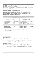
Inside the Checkpoint device, two switch banks set the deactivation antenna tuning. The recommended settings for the switch banks are shown below. See page 44 for tag deactivation guidelines. Switch Bank Settings SW1 SW2 Switches 1 - 6 OFF Switches 1 - 6 OFF Settings of 0pF to 47pF are recommended to achieve a maximum deactivation range. 41
-
 1
1 -
2
-
3
-
4
-
5
-
6
-
7
-
8
-
9
-
10
-
11
-
12
-
13
-
14
-
15
-
16
-
17
-
18
-
19
-
20
-
21
-
22
-
23
-
24
-
25
-
26
-
27
-
28
-
29
-
30
-
31
-
32
-
33
-
34
-
35
-
36
-
37
-
38
-
39
-
 40
40 -
 41
41 -
 42
42 -
 43
43 -
 44
44 -
 45
45 -
 46
46 -
 47
47 -
 48
48 -
 49
49 -
 50
50 -
51
-
52
-
53
-
54
-
55
-
56
-
57
-
58
-
59
-
60
-
61
-
62
-
63
-
64
-
65
-
66
-
67
-
68
 |
 |

41
Inside the Checkpoint device, two switch banks set the deactivation antenna
tuning.
The recommended settings for the switch banks are shown below.
See page 44 for tag deactivation guidelines.
Switch Bank Settings
SW1
SW2
Switches 1 - 6
OFF
Switches 1 - 6
OFF
Settings of 0pF to 47pF are recommended to achieve a maximum
deactivation range.