Honeywell NSLAN1 Installation Guide - Page 16
Nslan1 Leds
 |
View all Honeywell NSLAN1 manuals
Add to My Manuals
Save this manual to your list of manuals |
Page 16 highlights
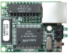
NSLAN1 Ethernet Board Installation Guide NSLAN1 LEDs NSLAN1 LEDs There are four LEDs on the NSLAN1 that can indicate if the NSLAN1 (Co-Box Micro) is malfunctioning. 1 (Red) > O O < (Top Green) 2 3 (Yellow) > O O < (Lower Green) 4 • LED 1 (Red): Error and diagnostic LED • LED 1 and LED 2 (Top Green) together indicate a series of diagnostic patterns: Note: If the LED 1 (Top Red) is on or blinking, the LED 2 ( Top Green) will give a diagnostics code. There is a fatal error and the NSLAN1 is not working. See below for error patterns. LED 1 (TOP RED) SOLID ON, LED 2 (TOP GREEN) BLINKING • 1x: EPROM checksum error • 2x: RAM error • 3x: Network controller error • 4x: EEPROM checksum error • 5x: Duplicated IP address on the network LED 1 (TOP RED) BLINKING, LED 2 (TOP GREEN) BLINKING • 4x: The network connection is faulty. This should only appear after power up. Even though the NSLAN1 is going into operation mode, the problem will potentially persist. • 5x: No DHCP response was received LED 2 (Top Green): Displays the status of channel 1: • Solid - Channel 1 is idle. • Blinking (1 sec. cycle) - the channel is connected over the network. This LED is also used for diagnostic and error detection when combined with LED 1(TOP Red), see above. LED 3 (Lower Yellow): • Solid - Channel 2 is idle. • Blinking (1 sec. cycle) - Channel is connected over the network. NSLAN1 Ethernet Board Installation Guide Document TD1164, Revision A 14 © 2005 Honeywell International
-
 1
1 -
2
-
3
-
4
-
5
-
6
-
7
-
8
-
9
-
10
-
 11
11 -
 12
12 -
 13
13 -
 14
14 -
 15
15 -
 16
16 -
 17
17 -
 18
18 -
 19
19
 |
 |
