Husqvarna TS142L Owner Manual - Page 26
CB DC BD AA
 |
View all Husqvarna TS142L manuals
Add to My Manuals
Save this manual to your list of manuals |
Page 26 highlights
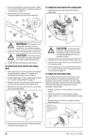
1. Put the cutting deck in transport position. Refer to To set the cutting deck in transport position or mow position on page 14. 2. Remove the bolt (A) by turning it counterclockwise and remove the blade (B). E B D To install the drive belt for the cutting deck 1. Install the drive belt (A) around the mandrel pulleys (B). C D A A C B WARNING: The blades on the cutting deck are sharp and can cause injury. Use protective gloves. 3. Install the new or sharpened blade and the bolt. CAUTION: The center hole (C) in the blade must align with the star (D) on the mandrel assembly (E). 4. Torque the bolt to 45-55 ft-lbs (62-75 Nm). To remove the drive belt for the cutting deck 1. Park the product on a level surface and engage the parking brake. Refer to To engage and disengage the parking brake on page 14. 2. Put the cutting deck in the lowest position. Refer to To set the cutting height on page 14. 3. Remove the dirt and grass around the mandrels and from the top surface of the cutting deck. 4. Remove the drive belt (A) from the clutch pulley (B) on the engine shaft. D B A CAUTION: Put the drive belt correctly in all the grooves on the cutting deck pulleys. The drive belt can become damaged if it is not installed correctly. 2. Install the drive belt around the idler pulleys (C). 3. Install the drive belt around the clutch pulley (D) on the engine shaft. 4. Put the cutting deck in transport position. Refer to To set the cutting deck in transport position or mow position on page 14. To adjust the anti-scalp rollers The anti-scalp rollers keep the cutting deck in the correct position on the ground and prevent lawn scalping in most terrain conditions. The anti-scalp rollers are adjusted correctly when they are slightly off the ground when the cutting deck is at the necessary cutting height. 1. Park the product on a level surface and stop the engine. 2. Adjust the product to the necessary cutting height. Refer to To set the cutting height on page 14. 3. Remove the nut, the bolt, the washer, and the anti-scalp roller. C 5. Remove the drive belt from the mandrel pulleys 3/4" (C) and the idler pulleys (D). 26 9/16" 1958 - 002 - 12.10.2022
-
 1
1 -
2
-
3
-
4
-
5
-
6
-
7
-
8
-
9
-
10
-
11
-
12
-
13
-
14
-
15
-
16
-
17
-
18
-
19
-
20
-
 21
21 -
 22
22 -
 23
23 -
 24
24 -
 25
25 -
 26
26 -
 27
27 -
 28
28 -
 29
29 -
 30
30 -
 31
31 -
32
-
33
-
34
-
35
-
36
-
37
-
38
-
39
-
40
-
41
-
42
-
43
-
44
-
45
-
46
-
47
-
48
-
49
-
50
-
51
-
52
-
53
-
54
-
55
-
56
-
57
-
58
-
59
-
60
-
61
-
62
-
63
-
64
-
65
-
66
-
67
-
68
-
69
-
70
-
71
-
72
-
73
-
74
-
75
-
76
-
77
-
78
-
79
-
80
 |
 |
