IBM FAStT500 User Guide
IBM FAStT500 - TotalStorage Storage Server RAID Controller Manual
 |
UPC - 087944520320
View all IBM FAStT500 manuals
Add to My Manuals
Save this manual to your list of manuals |
IBM FAStT500 manual content summary:
- IBM FAStT500 | User Guide - Page 1
IBM FAStT500 RAID Controller Enclosure Unit User's Guide IBM - IBM FAStT500 | User Guide - Page 2
- IBM FAStT500 | User Guide - Page 3
FAStT500 RAID Controller Enclosure Unit User's Guide - IBM FAStT500 | User Guide - Page 4
Note: Before using this information and the product it supports, be sure to read the general information under "Appendix B. Notices" on page 59. Second Edition (April . U.S. Government Users Restricted Rights-Use, duplication or disclosure restricted by GSA ADP Schedule Contract with IBM Corp. - IBM FAStT500 | User Guide - Page 5
Safety Before installing this product, read the Safety Information. Antes de instalar este produto, leia as , lue turvaohjeet kohdasta Safety Information. Avant d'installer ce produit, lisez les consignes de sécurité. Vor der Installation dieses Produkts die Sicherheitshinweise lesen. Prima di - IBM FAStT500 | User Guide - Page 6
este produto, leia as Informações sobre Segurança. Antes de instalar este producto, lea la información de seguridad. Läs säkerhetsinformationen innan du installerar den här produkten. iv IBM FAStT500 RAID Controller Enclosure Unit User's Guide - IBM FAStT500 | User Guide - Page 7
, or structural damage. • Disconnect the attached power cords, telecommunications systems, networks, and modems before you open the device covers, unless instructed otherwise in the installation and configuration procedures. • Connect and disconnect cables as described in the following table when - IBM FAStT500 | User Guide - Page 8
installed, note the following: • Do not remove the covers. Removing the covers of the laser product could result in exposure to hazardous laser radiation. There are no serviceable parts inside the device. • Use of controls 55 kg (121.2 lbs vi IBM FAStT500 RAID Controller Enclosure Unit User's Guide - IBM FAStT500 | User Guide - Page 9
Statememt 5 CAUTION: The power control button on the device and the power supply do not turn that has this label attached. There are no serviceable parts inside these components. If you suspect a problem with one of these parts, contact a service technician. Class 1 laser statement Class 1 Laser - IBM FAStT500 | User Guide - Page 10
viii IBM FAStT500 RAID Controller Enclosure Unit User's Guide - IBM FAStT500 | User Guide - Page 11
1 Back view 2 Fibre Channel connections 3 Interface ports 5 Host mini-hubs 6 Drive mini-hubs 6 Ethernet and RS-232 interface ports 7 Chapter 2. Operating the controller unit 9 Tasks overview 9 Accessing the controls 11 Turning on the power 12 Turning off the power 13 Monitoring status - IBM FAStT500 | User Guide - Page 12
supply 46 Mini-hubs 48 Servicing notes 49 Replacing a failed mini-hub 49 GBICs 51 Servicing notes 51 Replacing a failed GBIC 52 Appendix A. Getting help and technical assistance 55 Before you call 55 Using the documentation 55 x IBM FAStT500 RAID Controller Enclosure Unit User's Guide - IBM FAStT500 | User Guide - Page 13
Getting help and information from the World Wide Web 56 Software service and support 56 Hardware service and support 56 Appendix B. Notices 59 Federal Communications Commission (FCC) statement 61 Industry Canada Class A emission compliance statement 62 Australia and New Zealand Class A - IBM FAStT500 | User Guide - Page 14
xii IBM FAStT500 RAID Controller Enclosure Unit User's Guide - IBM FAStT500 | User Guide - Page 15
Figures Figure 1. IBM FAStT500 RAID Controller Enclosure Unit - front view 2 Figure 2. IBM FAStT500 RAID Controller Enclosure Unit - back view 3 Figure 3. Fibre Channel interface connections 3 Figure 4. Host side and drive side mini-hub ports (back view 6 Figure 5. Ethernet and RS-232 interface - IBM FAStT500 | User Guide - Page 16
and installing a fan and communications module 44 Figure 26. Power supply switch, ac power connectors, and indicator lights 46 Figure 27. Removing and installing a power supply CRU 48 Figure 28. Removing and installing a mini-hub 50 xiv IBM FAStT500 RAID Controller Enclosure Unit User's Guide - IBM FAStT500 | User Guide - Page 17
Tables Table 1. Tasks overview 9 Table 2. Indicator lights (front 16 Table 3. Indicator lights (back 19 Table 4. Mini-hub indicator lights (back 20 © Copyright IBM Corp. 2000, 2002 xv - IBM FAStT500 | User Guide - Page 18
xvi IBM FAStT500 RAID Controller Enclosure Unit User's Guide - IBM FAStT500 | User Guide - Page 19
unit Before using this book, you must install the hardware and software. For more information, refer to the IBM FAStT500 RAID Controller Enclosure Unit Installation Guide and the IBM FAStT Storage Manager Installation and Support Guide that come with the controller unit. How this book is organized - IBM FAStT500 | User Guide - Page 20
instruction or Document Format (PDF) on the IBM FAStT Storage Manager CD and on the World Wide Web at http://www.ibm.com/pc/support/. • IBM FAStT500 RAID Controller Enclosure Unit Installation Guide1 • IBM FAStT500 RAID Controller Enclosure Unit User's Guide (this book) • IBM FAStT Storage Manager - IBM FAStT500 | User Guide - Page 21
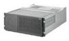
The IBM FAStT500 RAID Controller Enclosure Unit (referred to throughout this book as controller unit) is a high-performance unit that provides dual, redundant RAID controllers and Fibre Channel interfaces to both the host and drive channels. Controller unit overview The controller unit supports - IBM FAStT500 | User Guide - Page 22
for the controller unit. • Power supplies - Two removable units that contain the power supplies. • Fan and communications module - One removable unit that contains the power supply cooling fans, Ethernet ports, and RS-232 (serial) ports. 2 IBM FAStT500 RAID Controller Enclosure Unit User's Guide - IBM FAStT500 | User Guide - Page 23
Fan and communications module Drive side mini-hubs Power supply Power supply Figure 2. IBM FAStT500 RAID Controller Enclosure Unit - back view Fibre Channel connections When fully configured, the back of the controller unit can accommodate up to four host side and four drive side mini-hubs - IBM FAStT500 | User Guide - Page 24
installed, note the following: • Do not remove the covers. Removing the covers of the laser product could result in exposure to hazardous laser radiation. There are no serviceable parts inside the device. • Use of controls is well supported. 4 IBM FAStT500 RAID Controller Enclosure Unit User's Guide - IBM FAStT500 | User Guide - Page 25
. GBIC Fiber-optic cable After installing the cables, the Fibre Channel Arbitrated Loop is operational. For information about replacing mini-hubs, see "Mini-hubs" on page 48. For information about replacing GBICs, see "GBICs" on page 51. Interface ports The controller unit has the following types of - IBM FAStT500 | User Guide - Page 26
and drive interface ports, refer to the IBM FAStT500 RAID Controller Enclosure Unit Installation Guide. Host mini-hubs There are up to four host side mini-hubs, two per controller (see Figure 4). Mini-hubs 1 and 3 correspond to the top controller (Controller A) and mini-hubs 2 and 4 correspond to - IBM FAStT500 | User Guide - Page 27
ports if you want to directly manage the controllers. Use the RS-232 ports for diagnostic service. Figure 5 shows the location of these interface ports. RS-232 ports Controller B Controller A Ethernet ports Controller B Controller A Figure 5. Ethernet and RS-232 interface ports Chapter - IBM FAStT500 | User Guide - Page 28
8 IBM FAStT500 RAID Controller Enclosure Unit User's Guide - IBM FAStT500 | User Guide - Page 29
controller unit after it is installed. Table 1: Tasks overview Task Description See Accessing the controls To access the controller CRUs, battery, controller controller unit and are monitored by the storage-management software. Note: The indicator lights identify problems with the controller - IBM FAStT500 | User Guide - Page 30
"Checking the battery service date" on page 24 Preparing to move the controller unit You might need to move the controller unit to a new location or remove the chassis from its cabinet. "Preparing to move the controller unit" on page 25 10 IBM FAStT500 RAID Controller Enclosure Unit User's Guide - IBM FAStT500 | User Guide - Page 31
the bottom of the bezel out to release the pins; then slide the bezel down, as shown in the following figure. Bezel Figure 6. Removing the controller unit bezel 2 To replace the bezel, slip the top edge of the bezel under the lip on the chassis, then push the bottom of the - IBM FAStT500 | User Guide - Page 32
drive enclosure and each controller unit are on before turning on the main breaker. For instructions on powering up the drive enclosures, refer to the drive enclosure documentation. Note: Always wait Figure 8. Turning on and off the power 12 IBM FAStT500 RAID Controller Enclosure Unit User's Guide - IBM FAStT500 | User Guide - Page 33
controller unit fault indicator lights are lit. Use the proper troubleshooting or servicing procedure to correct the fault before turning off the power. This ensures that the controller lights on the controller unit are off. If any fault indicator lights are on, correct the problem before turning off - IBM FAStT500 | User Guide - Page 34
: • IBM FAStT Storage Manager Version 7.10 Installation and Support Guide • IBM FAStT Storage Manager Version 7.10 Concepts Guide The following IBM FAStT Storage Manager online help is available: • Enterprise Management Online Help • Subsystem Management Online Help 14 IBM FAStT500 RAID Controller - IBM FAStT500 | User Guide - Page 35
in Table 2 on page 16. 3 Check the indicator lights on the back of the controller unit, as shown in Figure 10 on page 18 and described in Table 3 on page replace the bezel; otherwise, run the storage-management software to diagnose and repair the problem. Chapter 2. Operating the controller unit 15 - IBM FAStT500 | User Guide - Page 36
Problem indicator Possible conditions indicated by the problem indicator1 Component: controller CRU Green On Off • No power to controller unit • No power to storage there is a memory fault indicating that the controller CRU has failed. 16 IBM FAStT500 RAID Controller Enclosure Unit User's Guide - IBM FAStT500 | User Guide - Page 37
2: Indicator lights (front) Indicator light Color Normal operation Problem indicator Possible conditions indicated by the problem indicator1 Component: controller fan Power Green On Off • No power to controller unit • No power to storage subsystem • Cables are loose or the switches are off - IBM FAStT500 | User Guide - Page 38
lights on the back of the controller unit are shown in Figure 10 and are described in Table 3 on page 19. Power supply fault Fan and communications module fault Power supply fault Figure 10. Controller unit indicator lights - back view 18 IBM FAStT500 RAID Controller Enclosure Unit User's Guide - IBM FAStT500 | User Guide - Page 39
module has failed or is installed incorrectly • Overtemperature condition Power supply Power supply Green On Off • No power to controller unit • No power to storage subsystem • Power supply has failed • Overtemperature condition 1 Always use the storage-management software to identify the - IBM FAStT500 | User Guide - Page 40
hub indicator lights (back) Icon Indicator light Color Normal operation Problem indicator Possible condition indicated by the problem indicator Component: mini-hub (host-side) Fault Amber Off port is unoccupied, the light is on. 20 IBM FAStT500 RAID Controller Enclosure Unit User's Guide - IBM FAStT500 | User Guide - Page 41
Icon Indicator light Color Normal operation Problem indicator Possible condition indicated by the problem indicator Component: mini-hub (drive-side) Fault Amber Off On Mini-hub or GBIC has failed. Note: If a drive-side mini-hub is not connected to a controller, this fault light is always - IBM FAStT500 | User Guide - Page 42
rises to 70°C (158°F). See Figure 13 for the location of the controller fan fault indicator. If both power supplies shut down, the fault indicator cannot come on. Controller fan fault indicator Figure 13. Overtemperature indicator 22 IBM FAStT500 RAID Controller Enclosure Unit User's Guide - IBM FAStT500 | User Guide - Page 43
controller unit for faults or damage. Use the storage-management software to check the overall status of the controller your system serviced. 2 controller unit are on before turning on the main breaker. For instructions on powering up the drive enclosures, refer to the drive enclosure documentation - IBM FAStT500 | User Guide - Page 44
is time to replace the battery, install a new battery using the procedure described in "Replacing a failed battery" on page 35. • If it is not time to replace the battery, replace the controller unit bezel, as shown in Figure 7 on page 11. 24 IBM FAStT500 RAID Controller Enclosure Unit User's Guide - IBM FAStT500 | User Guide - Page 45
controller unit, refer to the IBM FAStT500 RAID Controller Enclosure Unit Installation Guide. Removing and installing the that all amber fault indicator lights on the controller unit are off. If any fault indicator lights are on, correct the problem before turning off the power. For more information - IBM FAStT500 | User Guide - Page 46
install controller unit; then, remove the two screws from the inside front of the controller unit. Save the four screws for later. Attention: Do not remove the black hex head screws. These secure the rails that support your controller unit. 26 IBM FAStT500 RAID Controller Enclosure Unit User's Guide - IBM FAStT500 | User Guide - Page 47
. You are finished with this procedure. 12 If you are moving the controller unit to another cabinet, remove the support rails and power cords from the old cabinet and install them in the new one. 13 To replace the controller unit and components, using the proper cautions, reverse Step 1 on page 25 - IBM FAStT500 | User Guide - Page 48
i Make sure that all amber fault indicator lights on the controller unit are off. If any fault indicator lights are on, correct the problem. j Replace the controller unit bezel. k Check the indicator lights. 28 IBM FAStT500 RAID Controller Enclosure Unit User's Guide - IBM FAStT500 | User Guide - Page 49
storage server cover or any metal surface. • Take additional care when handling devices during cold weather because heating reduces indoor humidity and increases static electricity. RAID Controller The controller unit supports redundant array of independent disks (RAID) technology. The controller - IBM FAStT500 | User Guide - Page 50
. • Firmware between the two controllers is automatically synchronized when you replace a controller. Replacing a failed controller When instructed by the storage-management software, replace a controller CRU using the following procedure. 30 IBM FAStT500 RAID Controller Enclosure Unit User's Guide - IBM FAStT500 | User Guide - Page 51
through the storage-management software. 2 Using Figure 16 on page 31 as a guide, remove the controller that has failed. a Squeeze the two center tabs and open the handles. b Remove the controller. c Close the handles and snap into place. Figure 16. Removing and installing a controller CRU Attention - IBM FAStT500 | User Guide - Page 52
additional cache memory in a controller The controller comes with 256 MB of cache memory installed. You can add an additional 256 MB dual inline memory module (DIMM) for a total of 512 MB cache, with the IBM FAStT500 256 MB Cache option. 32 IBM FAStT500 RAID Controller Enclosure Unit User's Guide - IBM FAStT500 | User Guide - Page 53
unit a few inches. Grasp both sides of the controller to completely remove it from the controller unit. Controller Controller unit Levers 2 Remove both screws from the top cover of the controller; then, lift the cover and set it aside to install after you upgrade your cache. Top cover screws - IBM FAStT500 | User Guide - Page 54
they lock and secure the DIMM into place. DIMM latches in closed position 6 Install the top cover that you removed in Step 2 on page 33. Install the controller back into the controller unit by reversing the procedure in Step 1 on page 33. 34 IBM FAStT500 RAID Controller Enclosure Unit User's Guide - IBM FAStT500 | User Guide - Page 55
problems (for example, loss of battery power to the controllers or batteries not charging properly), the controller unit might have defective components or connections. Check the storage-management software for indications of other component failures. Replacing a failed battery When instructed - IBM FAStT500 | User Guide - Page 56
support information 3 Fill in the following information: • Date of Installation controller unit bezel, as shown in Figure 6 on page 11. Attention: Be careful when removing the battery. The battery weighs approximately 6.4 kg (14 lbs). 36 IBM FAStT500 RAID Controller Enclosure Unit User's Guide - IBM FAStT500 | User Guide - Page 57
There are no serviceable parts inside these components. If you suspect a problem with one of these parts, contact a service technician. 5 Using Figure 19 as a guide, remove the handle Captive screws Figure 19. Removing and installing a battery Chapter 3. Replacing controller unit components 37 - IBM FAStT500 | User Guide - Page 58
charging. 10 Reset the battery installation date using the storage-management software. The software continues to issue battery-related errors if the installation date is not reset. CONTAINS SEALED LEAD BATTERY. BATTERY MUST BE RECYCLED. Pb 38 IBM FAStT500 RAID Controller Enclosure Unit User's Guide - IBM FAStT500 | User Guide - Page 59
the controllers from overheating until you can replace the entire controller fan. To prevent cooling problems, the controller unit obstructions. Figure 21 shows the controller unit air flow. Make sure your installation site allows adequate ventilation to the controller unit during operation. Note: - IBM FAStT500 | User Guide - Page 60
still experience problems, the controller unit might have defective components or connections. Check the storage-management software for indications of other component failures. Replacing a failed controller fan When instructed by the storage-management software, replace a controller fan. Attention - IBM FAStT500 | User Guide - Page 61
fan. b Pull firmly on the bottom lip to remove the fan. Figure 22. Removing and installing the controller fan 4 Install the new controller fan. a Slide the new controller fan all the way into the slot. b Press down on the lever and snap the lever into place. 5 The following figure shows the - IBM FAStT500 | User Guide - Page 62
page 15. • If you replace the fan and communications module and still experience problems, the controller unit might have defective components or connections. Check the storagemanagement software for indications of other component failures. 42 IBM FAStT500 RAID Controller Enclosure Unit User's Guide - IBM FAStT500 | User Guide - Page 63
fan and communications module When instructed by the storage-management or diagnostic software, replace a fan and communications unit. Attention: To prevent damage to the controller unit circuitry, do not operate the controller unit without adequate ventilation to the controllers. If it will take - IBM FAStT500 | User Guide - Page 64
controller unit. 5 Install controller unit until you can replace the failed fan and communications module with a new one. 7 Reconnect the interface cables that you disconnected in Step 3 on page 43, to the new fan and communications module. 44 IBM FAStT500 RAID Controller Enclosure Unit User's Guide - IBM FAStT500 | User Guide - Page 65
controller unit if the other power supply is turned off or malfunctions. Servicing notes Consider the following when servicing , the controller also resumes operation. After you manually cycle the off all power to the controller unit. Note: There is a serious problem if the air temperature inside - IBM FAStT500 | User Guide - Page 66
problems, the controller unit might have defective components or connections. Check the storage-management software for indications of other component failures. Replacing a failed power supply When instructed by the storage-management 46 IBM FAStT500 RAID Controller Enclosure Unit User's Guide - IBM FAStT500 | User Guide - Page 67
. If you suspect a problem with one of these parts, contact a service technician. 2 Using Figure 27 on page 48 as a guide, remove the failed power supply. Using the pull handle, lift up and pull out to release the power supply; then, slide it out. Chapter 3. Replacing controller unit components 47 - IBM FAStT500 | User Guide - Page 68
-hub has two ports. A Gigabit Interface Converter (GBIC) is installed in a mini-hub port. Then a fiberoptic interface cable is connected into the GBIC. For more information, see "Fibre Channel connections" on page 3 and "GBICs" on page 51. 48 IBM FAStT500 RAID Controller Enclosure Unit User's Guide - IBM FAStT500 | User Guide - Page 69
servicing mini-hubs: • You can hot swap (replace) a failed mini-hub while the controller still experience problems, the controller unit might a failed mini-hub When instructed by the storage-management software, replace a mini-hub cables. Note: If you are using IBM GBICs, you must remove the fiber- - IBM FAStT500 | User Guide - Page 70
mini-hubs and ports. Mini-hub Captive screw Mini-hub ports Figure 28. Removing and installing a mini-hub Attention: When you handle static-sensitive devices, take precautions to avoid the appropriate slot; then, tighten the captive screw. 50 IBM FAStT500 RAID Controller Enclosure Unit User's Guide - IBM FAStT500 | User Guide - Page 71
problem is indicated, use the storage-management software to check the controller Servicing notes Consider the following when servicing GBICs: • You can hot swap (replace) a failed GBIC while the controller unit is in operation. • The operational loop performance is not affected when you install - IBM FAStT500 | User Guide - Page 72
and avoid direct exposure to the beam. When instructed by the storage-management software, replace a GBIC in the mini-hub. IBM GBICs, you must remove the fiber-optic cable from the GBIC before you can remove the GBIC from the mini-hub port. 52 IBM FAStT500 RAID Controller Enclosure Unit User's Guide - IBM FAStT500 | User Guide - Page 73
. Pull the failed GBIC from its mini-hub port. GBIC Fiber-optic cable 3 Insert the protective cap on the GBIC. Protective cap GBIC Chapter 3. Replacing controller unit components 53 - IBM FAStT500 | User Guide - Page 74
Remove the protective cap from the GBIC. b If the GBIC you are installing has a metal latch, move the metal latch to the unlocked (center) problem is indicated, use the storage-management software to check the controller unit status. 54 IBM FAStT500 RAID Controller Enclosure Unit User's Guide - IBM FAStT500 | User Guide - Page 75
the problem yourself: • Check all cables to make sure that they are connected. • Check the power switches to make sure that the system is turned on. • Use the troubleshooting information in your system documentation, and use the diagnostic tools that come with your system. • Go to the IBM Support - IBM FAStT500 | User Guide - Page 76
You can receive hardware service through IBM Integrated Technology Services or through your IBM reseller, if your reseller is authorized by IBM to provide warranty service. Go to http://www.ibm.com/planetwide/ for support telephone numbers. 56 IBM FAStT500 RAID Controller Enclosure Unit User's Guide - IBM FAStT500 | User Guide - Page 77
In the U.S. and Canada, hardware service and support is available 24 hours a day, 7 days a week. In the U.K., these services are available Monday through Friday, from 9 a.m. to 6 p.m. Appendix A. Getting help and technical assistance 57 - IBM FAStT500 | User Guide - Page 78
58 IBM FAStT500 RAID Controller Enclosure Unit User's Guide - IBM FAStT500 | User Guide - Page 79
the user's responsibility to evaluate and verify the operation of any non-IBM product, program, or service. IBM may have patents or pending patent applications covering subject matter described in this document. The furnishing of this document does not give you any license to these patents. You can - IBM FAStT500 | User Guide - Page 80
Documentation related to restricted rights - Use, duplication or disclosure is subject to restrictions set forth in GSA ADP Schedule Contract with IBM company, product, or service names may be the trademarks or service marks of others. Important IBM FAStT500 RAID Controller Enclosure Unit User's Guide - IBM FAStT500 | User Guide - Page 81
IBM FAStT200 and FAStT200 HA Storage Servers: Installation and User's Guide IBM makes no representations or warranties with respect to non-IBM products. Support (if any) for the non-IBM energy and, if not installed and used in accordance with the instruction manual, may cause harmful interference - IBM FAStT500 | User Guide - Page 82
resulting from a nonrecommended modification of the product, including the fitting of non-IBM option cards. This product has been tested and found to comply with the limits in which case the user may be required to take adequate measures. 62 IBM FAStT500 RAID Controller Enclosure Unit User's Guide - IBM FAStT500 | User Guide - Page 83
Taiwan electrical emission statement Japanese Voluntary Control Council for Interference (VCCI) statement Power cords For your safety, IBM provides a power cord with a grounded attachment plug to use with this IBM product. To avoid electrical shock, always use the power cord and plug with a properly - IBM FAStT500 | User Guide - Page 84
the country in which the equipment will be installed. IBM power cords for a specific country or region are usually available only in that Philippines, Saudi Arabia, Suriname, Taiwan, Trinidad (West Indies), United States of America, Venezuela 64 IBM FAStT500 RAID Controller Enclosure Unit User's Guide - IBM FAStT500 | User Guide - Page 85
Index A ac power cord locations 12 air ventilation around controller unit 39 auto-synchronization of firmware on control- ler CRUs 30 B back view of controller unit 2 battery charge indicator 16 checking service date 24 date of installation 24 date of manufacture 24 fault indicator lights 16 full - IBM FAStT500 | User Guide - Page 86
mini-hub 19, 20 overview 15 power supply 18, 19, 46 M maintenance, battery 35 manufacture date, battery 24 memory, cache and battery backup 35 memory, installing 256 MB cache upgrade 33 mini-hub described 48 drive side 6 host side 6 66 IBM FAStT500 RAID Controller Enclosure Unit User's Guide - IBM FAStT500 | User Guide - Page 87
) ports 7 service date of battery 24 servicing battery 39 shutdown sequence for controller unit 13, 25 static-sensitive devices 29 static-sensitive devices, handling 29 status indicator lights on controller CRU 16 status of controller unit, monitoring with soft- ware 14 storage-management software - IBM FAStT500 | User Guide - Page 88
checking data in cache 35 monitoring controller unit status 14 T temperature problems controller unit 39 power supply 45 trademarks 60 turning off power 13 turning on power 12 V ventilation around controller unit 39 W warranty statements 59 68 IBM FAStT500 RAID Controller Enclosure Unit User's Guide - IBM FAStT500 | User Guide - Page 89
- IBM FAStT500 | User Guide - Page 90
IBM@ Part Number: 48P9847 Printed in the United States of America on recycled paper containing 10% recovered post-consumer fiber.
-
 1
1 -
 2
2 -
 3
3 -
 4
4 -
 5
5 -
 6
6 -
 7
7 -
8
-
9
-
10
-
11
-
12
-
13
-
14
-
15
-
16
-
17
-
18
-
19
-
20
-
21
-
22
-
23
-
24
-
25
-
26
-
27
-
28
-
29
-
30
-
31
-
32
-
33
-
34
-
35
-
36
-
37
-
38
-
39
-
40
-
41
-
42
-
43
-
44
-
45
-
46
-
47
-
48
-
49
-
50
-
51
-
52
-
53
-
54
-
55
-
56
-
57
-
58
-
59
-
60
-
61
-
62
-
63
-
64
-
65
-
66
-
67
-
68
-
69
-
70
-
71
-
72
-
73
-
74
-
75
-
76
-
77
-
78
-
79
-
80
-
81
-
82
-
83
-
84
-
85
-
86
-
87
-
88
-
89
-
90
 |
 |

IBM
IBM FAStT500 RAID Controller
Enclosure Unit
User’s Guide