IBM FAStT500 User Guide - Page 64
module is inserted all the way into the chassis and secured in place.
 |
UPC - 087944520320
View all IBM FAStT500 manuals
Add to My Manuals
Save this manual to your list of manuals |
Page 64 highlights
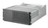
4 Using Figure 25 as a guide, remove the failed fan and communications CRU from the controller unit. Captive screws Figure 25. Removing and installing a fan and communications module a Using a flat-blade screwdriver, loosen the three captive screws on the fan and communications module. b Use the pull handle to slide the module out of the slot a few inches. c Grasp the sides of the module with both hands and remove it from the controller unit. 5 Install the new fan and communications module. Push the new fan and communications module all the way into its chassis slot. Use a flat-blade screwdriver to tighten the three captive screws on the new module, securing it into place. 6 Check the fan and communications indicator light (see Figure 24 on page 43). • If the amber fault indicator light is on, make sure that the fan and communications module is inserted all the way into the chassis and secured in place. • If the fault indicator light remains on, one or both fans inside the fan and communications module might be malfunctioning. Replace the failed fan and communications module with a spare, if available. If not, shut down the controller unit until you can replace the failed fan and communications module with a new one. 7 Reconnect the interface cables that you disconnected in Step 3 on page 43, to the new fan and communications module. 44 IBM FAStT500 RAID Controller Enclosure Unit User's Guide
-
 1
1 -
2
-
3
-
4
-
5
-
6
-
7
-
8
-
9
-
10
-
11
-
12
-
13
-
14
-
15
-
16
-
17
-
18
-
19
-
20
-
21
-
22
-
23
-
24
-
25
-
26
-
27
-
28
-
29
-
30
-
31
-
32
-
33
-
34
-
35
-
36
-
37
-
38
-
39
-
40
-
41
-
42
-
43
-
44
-
45
-
46
-
47
-
48
-
49
-
50
-
51
-
52
-
53
-
54
-
55
-
56
-
57
-
58
-
 59
59 -
 60
60 -
 61
61 -
 62
62 -
 63
63 -
 64
64 -
 65
65 -
 66
66 -
 67
67 -
 68
68 -
 69
69 -
70
-
71
-
72
-
73
-
74
-
75
-
76
-
77
-
78
-
79
-
80
-
81
-
82
-
83
-
84
-
85
-
86
-
87
-
88
-
89
-
90
 |
 |
