IBM FAStT500 User Guide - Page 59
Controller fan, impede air flow and cause one or more components in the controller unit to overheat.
 |
UPC - 087944520320
View all IBM FAStT500 manuals
Add to My Manuals
Save this manual to your list of manuals |
Page 59 highlights
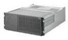
Attention: Use proper facilities to recycle the used battery CRU. If the battery CRU is physically damaged or leaking electrolyte gel, DO NOT ship it to a recycling center. The battery contains sealed lead acid batteries that might be considered hazardous material. You must handle this unit in accordance with all applicable local and federal regulations. 11 Dispose of the used battery CRU according to local and federal regulations, which might include hazardous material handling procedures. Controller fan The controller fan is a single, removable unit containing two cooling fans and temperature monitoring circuitry. The controller fan plugs directly into a slot on the front of the controller unit, to the left of the controllers (see Figure 22 on page 41). Five indicator lights provide overall system status information (see Figure 23 on page 41). The dual fans in the controller fan provide a redundant cooling system to both controller CRUs. If one fan fails, the other continues to operate, providing sufficient air circulation to prevent the controllers from overheating until you can replace the entire controller fan. To prevent cooling problems, the controller unit must have proper air circulation throughout the chassis. Cooling problems include any malfunctions or obstructions that impede air flow and cause one or more components in the controller unit to overheat. Make sure that the ambient air temperature around the controller unit is within the environmental requirements. To boost air circulation, the controller unit chassis has air vents along its top and sides. These vents serve as air intake and exhaust passages. Always keep vents clean and free of obstructions. Figure 21 shows the controller unit air flow. Make sure your installation site allows adequate ventilation to the controller unit during operation. Note: Allow at least 60 cm (2 ft) of clearance in front of and behind the controller unit for proper ventilation. Figure 21. Controller unit airflow Chapter 3. Replacing controller unit components 39
-
 1
1 -
2
-
3
-
4
-
5
-
6
-
7
-
8
-
9
-
10
-
11
-
12
-
13
-
14
-
15
-
16
-
17
-
18
-
19
-
20
-
21
-
22
-
23
-
24
-
25
-
26
-
27
-
28
-
29
-
30
-
31
-
32
-
33
-
34
-
35
-
36
-
37
-
38
-
39
-
40
-
41
-
42
-
43
-
44
-
45
-
46
-
47
-
48
-
49
-
50
-
51
-
52
-
53
-
 54
54 -
 55
55 -
 56
56 -
 57
57 -
 58
58 -
 59
59 -
 60
60 -
 61
61 -
 62
62 -
 63
63 -
 64
64 -
65
-
66
-
67
-
68
-
69
-
70
-
71
-
72
-
73
-
74
-
75
-
76
-
77
-
78
-
79
-
80
-
81
-
82
-
83
-
84
-
85
-
86
-
87
-
88
-
89
-
90
 |
 |
