IBM x3650 User Guide - Page 33
Rear view, Systems-management Ethernet connector - m2 server
 |
UPC - 883436059565
View all IBM x3650 manuals
Add to My Manuals
Save this manual to your list of manuals |
Page 33 highlights
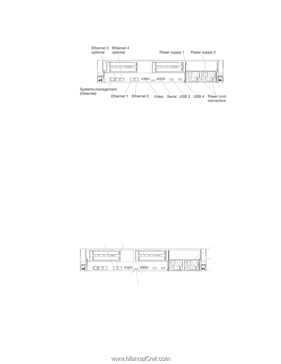
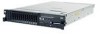
Rear view The following illustration shows the connectors on the rear of the server. Ethernet connectors: Use any of these connectors to connect the server to a network. Power-cord connector: Connect the power cord to this connector. USB connectors: Connect a USB device, such as USB mouse, keyboard, or other USB device, to any of these connectors. Serial connector: Connect a 9-pin serial device to this connector. The serial port is shared with the integrated management module (IMM). The IMM can take control of the shared serial port to perform text console redirection and to redirect serial traffic, using Serial over LAN (SOL). Video connector: Connect a monitor to this connector. The video connectors on the front and rear of the server can be used simultaneously. Note: The maximum video resolution is 1600 x 1200 at 75 MHz. Systems-management Ethernet connector: Use this connector to connect the server to a network for systems-management information control. This connector is used only by the IMM. The following illustration shows the LEDs on the rear of the server. Ethernet Ethernet activity LED link LED AC power LED (green) DC power LED (green) Power-on System-error LED (green) LED (amber) Locator LED (blue) Power-supply error LED (amber) Ethernet activity LEDs: When these LEDs are lit, they indicate that the server is transmitting to or receiving signals from the Ethernet LAN that is connected to the Ethernet port. Ethernet link LEDs: When these LEDs are lit, they indicate that there is an active link connection on the 10BASE-T, 100BASE-TX, or 1000BASE-TX interface for the Ethernet port. Chapter 1. The System x3650 M2 Type 7947 server 17
-
 1
1 -
2
-
3
-
4
-
5
-
6
-
7
-
8
-
9
-
10
-
11
-
12
-
13
-
14
-
15
-
16
-
17
-
18
-
19
-
20
-
21
-
22
-
23
-
24
-
25
-
26
-
27
-
 28
28 -
 29
29 -
 30
30 -
 31
31 -
 32
32 -
 33
33 -
 34
34 -
 35
35 -
 36
36 -
 37
37 -
 38
38 -
39
-
40
-
41
-
42
-
43
-
44
-
45
-
46
-
47
-
48
-
49
-
50
-
51
-
52
-
53
-
54
-
55
-
56
-
57
-
58
-
59
-
60
-
61
-
62
-
63
-
64
-
65
-
66
-
67
-
68
-
69
-
70
-
71
-
72
-
73
-
74
-
75
-
76
-
77
-
78
-
79
-
80
-
81
-
82
-
83
-
84
-
85
-
86
-
87
-
88
-
89
-
90
-
91
-
92
-
93
-
94
-
95
-
96
-
97
-
98
-
99
-
100
-
101
-
102
-
103
-
104
-
105
-
106
-
107
-
108
-
109
-
110
-
111
-
112
-
113
-
114
-
115
-
116
-
117
-
118
-
119
-
120
-
121
-
122
-
123
-
124
-
125
-
126
-
127
-
128
-
129
-
130
-
131
-
132
-
133
-
134
-
135
-
136
-
137
-
138
-
139
-
140
-
141
-
142
-
143
-
144
-
145
-
146
-
147
-
148
-
149
-
150
-
151
-
152
-
153
-
154
-
155
-
156
-
157
-
158
-
159
-
160
-
161
-
162
-
163
-
164
-
165
-
166
 |
 |