IBM x3650 User Guide - Page 59
Removing the cover - rails
 |
UPC - 883436059565
View all IBM x3650 manuals
Add to My Manuals
Save this manual to your list of manuals |
Page 59 highlights
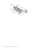
Removing the cover The following illustration shows how to remove the cover. Important: Before you install optional hardware, make sure that the server is working correctly. Start the server, and make sure that the operating system starts, if an operating system is installed, or that a 19990305 error code is displayed, indicating that an operating system was not found but the server is otherwise working correctly. If the server is not working correctly, see the Problem Determination and Service Guide for diagnostic information. To remove the cover, complete the following steps: 1. Read the safety information that begins on page vii and "Installation guidelines" on page 36. 2. If you are planning to view the error LEDs that are on the system board and components, leave the server connected to power and go directly to step 4. 3. If you are planning to install or remove a microprocessor, memory module, PCI adapter, battery, or other non-hot-swap optional device, turn off the server and all attached devices and disconnect all external cables and power cords (see "Turning off the server" on page 21). 4. Press down on the left and right side latches and slide the server out of the rack enclosure until both slide rails lock. Note: You can reach the cables on the rear of the server when the server is in the locked position. 5. Press the blue latch 1 on the end of the cover-release latch and lift the cover-release latch 2 . Slide the cover toward the rear 3 and lift the cover off the server. Set the cover aside. Attention: For proper cooling and airflow and to avoid damaging server components, replace the cover before you turn on the server. If you operate the server for extended periods of time (over 30 minutes) with the cover removed, the IMM turns off the server. Chapter 2. Installing optional devices 43
-
 1
1 -
2
-
3
-
4
-
5
-
6
-
7
-
8
-
9
-
10
-
11
-
12
-
13
-
14
-
15
-
16
-
17
-
18
-
19
-
20
-
21
-
22
-
23
-
24
-
25
-
26
-
27
-
28
-
29
-
30
-
31
-
32
-
33
-
34
-
35
-
36
-
37
-
38
-
39
-
40
-
41
-
42
-
43
-
44
-
45
-
46
-
47
-
48
-
49
-
50
-
51
-
52
-
53
-
 54
54 -
 55
55 -
 56
56 -
 57
57 -
 58
58 -
 59
59 -
 60
60 -
 61
61 -
 62
62 -
 63
63 -
 64
64 -
65
-
66
-
67
-
68
-
69
-
70
-
71
-
72
-
73
-
74
-
75
-
76
-
77
-
78
-
79
-
80
-
81
-
82
-
83
-
84
-
85
-
86
-
87
-
88
-
89
-
90
-
91
-
92
-
93
-
94
-
95
-
96
-
97
-
98
-
99
-
100
-
101
-
102
-
103
-
104
-
105
-
106
-
107
-
108
-
109
-
110
-
111
-
112
-
113
-
114
-
115
-
116
-
117
-
118
-
119
-
120
-
121
-
122
-
123
-
124
-
125
-
126
-
127
-
128
-
129
-
130
-
131
-
132
-
133
-
134
-
135
-
136
-
137
-
138
-
139
-
140
-
141
-
142
-
143
-
144
-
145
-
146
-
147
-
148
-
149
-
150
-
151
-
152
-
153
-
154
-
155
-
156
-
157
-
158
-
159
-
160
-
161
-
162
-
163
-
164
-
165
-
166
 |
 |
