IBM x3650 User Guide - Page 43
Jumper number, Jumper setting, Notes, Switch, number, Default position, Description - bios
 |
UPC - 883436059565
View all IBM x3650 manuals
Add to My Manuals
Save this manual to your list of manuals |
Page 43 highlights
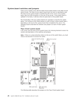
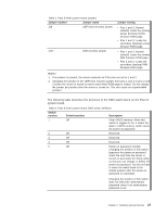
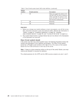
Table 3. Pass 8 level system board jumpers Jumper number Jumper name J29 UEFI boot recovery jumper J147 IMM recovery jumper Jumper setting v Pins 1 and 2: Normal (default) Loads the primary server (formerly BIOS) firmware ROM page. v Pins 2 and 3: Loads the secondary (backup) server firmware ROM page. v Pins 1 and 2: Normal (default) Loads the primary IMM firmware ROM page. v Pins 2 and 3: Loads the secondary (backup) IMM firmware ROM page. Notes: 1. If no jumper is present, the server responds as if the pins are set to 1 and 2. 2. Changing the position of the UEFI boot recovery jumper from pins 1 and 2 to pins 2 and 3 before the server is turned on alters which flash ROM page is loaded. Do not change the jumper pin position after the server is turned on. This can cause an unpredictable problem. The following table describes the functions of the SW3 switch block on the Pass 8 system board. Table 4. Pass 8 level system board SW3 switch definition Switch number Default position Description 1 Off Clear CMOS memory. When this switch is toggled to On, it clears the data in CMOS memory, which clears the power-on password. 2 Off Reserved. 3 Off Reserved. 4 Off Reserved. 5 Off Power-on password override. Changing the position of this switch bypasses the power-on password check the next time the server is turned on and starts the Setup utility so that you can change or delete the power-on password. You do not have to move the switch back to the default position after the power-on password in overridden. Changing the position of this switch does not affect the administrator password check if an administrator password is set. Chapter 2. Installing optional devices 27
-
 1
1 -
2
-
3
-
4
-
5
-
6
-
7
-
8
-
9
-
10
-
11
-
12
-
13
-
14
-
15
-
16
-
17
-
18
-
19
-
20
-
21
-
22
-
23
-
24
-
25
-
26
-
27
-
28
-
29
-
30
-
31
-
32
-
33
-
34
-
35
-
36
-
37
-
 38
38 -
 39
39 -
 40
40 -
 41
41 -
 42
42 -
 43
43 -
 44
44 -
 45
45 -
 46
46 -
 47
47 -
 48
48 -
49
-
50
-
51
-
52
-
53
-
54
-
55
-
56
-
57
-
58
-
59
-
60
-
61
-
62
-
63
-
64
-
65
-
66
-
67
-
68
-
69
-
70
-
71
-
72
-
73
-
74
-
75
-
76
-
77
-
78
-
79
-
80
-
81
-
82
-
83
-
84
-
85
-
86
-
87
-
88
-
89
-
90
-
91
-
92
-
93
-
94
-
95
-
96
-
97
-
98
-
99
-
100
-
101
-
102
-
103
-
104
-
105
-
106
-
107
-
108
-
109
-
110
-
111
-
112
-
113
-
114
-
115
-
116
-
117
-
118
-
119
-
120
-
121
-
122
-
123
-
124
-
125
-
126
-
127
-
128
-
129
-
130
-
131
-
132
-
133
-
134
-
135
-
136
-
137
-
138
-
139
-
140
-
141
-
142
-
143
-
144
-
145
-
146
-
147
-
148
-
149
-
150
-
151
-
152
-
153
-
154
-
155
-
156
-
157
-
158
-
159
-
160
-
161
-
162
-
163
-
164
-
165
-
166
 |
 |