IBM x3650 User Guide - Page 79
Installing a SAS/SATA 4 Pac HDD option - front bezel
 |
UPC - 883436059565
View all IBM x3650 manuals
Add to My Manuals
Save this manual to your list of manuals |
Page 79 highlights
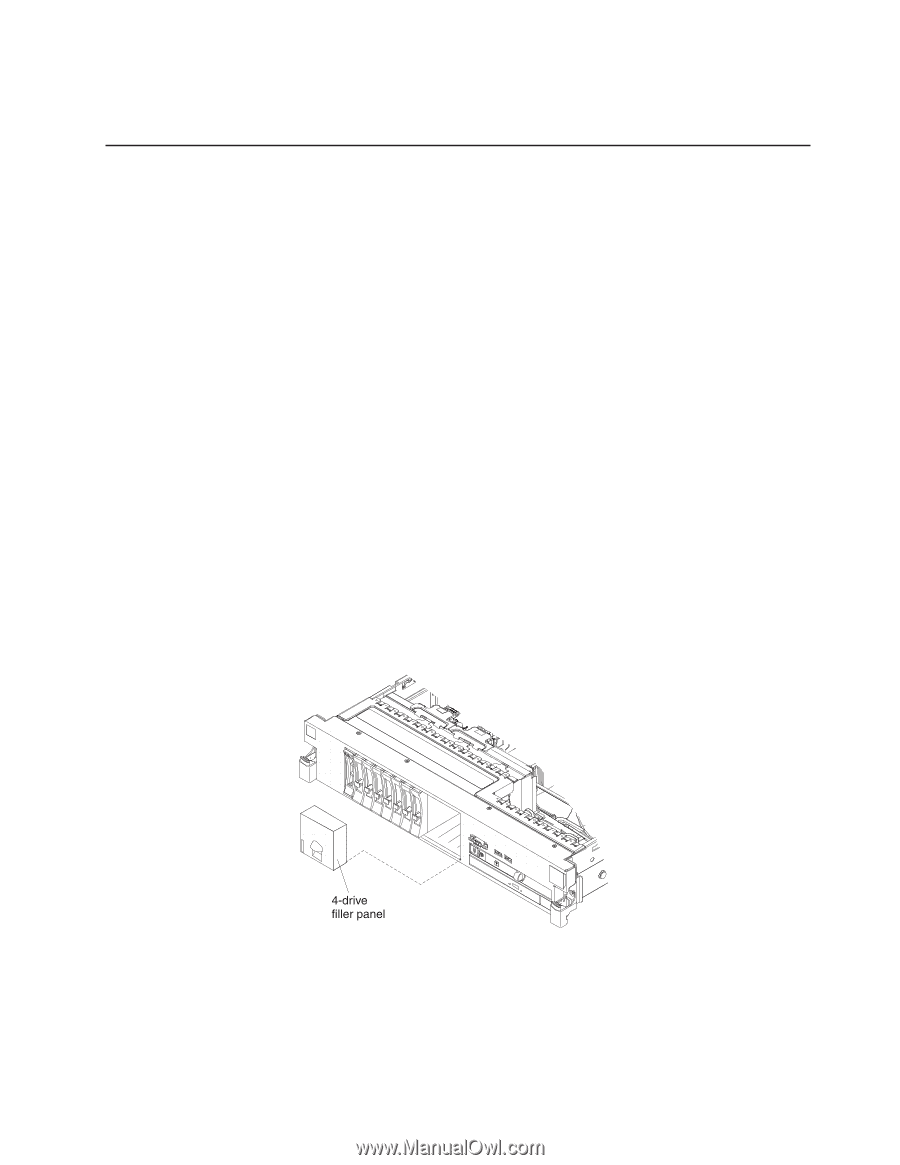
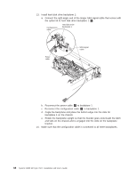
If you have other devices to install or remove, do so now. Otherwise, go to "Completing the installation" on page 106. Installing a SAS/SATA 4 Pac HDD option If the server is a 12-drive-capable model with eight hard disk drive bays installed, you can install an IBM System x3650 M2 Hot-swap SAS/SATA 4 Pac HDD option. See http://www.ibm.com/servers/eserver/serverproven/compat/us/ for a list of supported optional devices. To order a SAS/SATA 4 Pac HDD option, contact your IBM marketing representative or authorized reseller. The SAS/SATA 4 Pac HDD option kit contains the following components: v One 2.5-inch hard disk drive backplane v Two SAS signal cables (one cable has a right-angle connector) v One internal power cable v One SAS expander card v Four hard disk drive bay filler panels v SAS controller front retention bracket v Remote battery cable, interposer card, and screw To install a 4-disk-drive optional expansion device in a 12-drive-capable server model, complete the following steps: 1. Read the safety information that begins on page vii and "Installation guidelines" on page 36. 2. Turn off the server and disconnect all power cords and external cables (see "Turning off the server" on page 21). 3. Remove the server cover (see "Removing the cover" on page 43). 4. Remove the 4-drive filler panel that is to the right of drive bay 8, beneath the IDs 8 - 11 on the front bezel. 5. To obtain more working room, remove fans 2 and 3 (see "Removing a hot-swap fan" on page 89). 6. Pull the hard disk drives or fillers out of the server slightly to disengage them from the backplanes. For more information, see"Removing a hard disk drive" on page 58. Chapter 2. Installing optional devices 63
-
 1
1 -
2
-
3
-
4
-
5
-
6
-
7
-
8
-
9
-
10
-
11
-
12
-
13
-
14
-
15
-
16
-
17
-
18
-
19
-
20
-
21
-
22
-
23
-
24
-
25
-
26
-
27
-
28
-
29
-
30
-
31
-
32
-
33
-
34
-
35
-
36
-
37
-
38
-
39
-
40
-
41
-
42
-
43
-
44
-
45
-
46
-
47
-
48
-
49
-
50
-
51
-
52
-
53
-
54
-
55
-
56
-
57
-
58
-
59
-
60
-
61
-
62
-
63
-
64
-
65
-
66
-
67
-
68
-
69
-
70
-
71
-
72
-
73
-
 74
74 -
 75
75 -
 76
76 -
 77
77 -
 78
78 -
 79
79 -
 80
80 -
 81
81 -
 82
82 -
 83
83 -
 84
84 -
85
-
86
-
87
-
88
-
89
-
90
-
91
-
92
-
93
-
94
-
95
-
96
-
97
-
98
-
99
-
100
-
101
-
102
-
103
-
104
-
105
-
106
-
107
-
108
-
109
-
110
-
111
-
112
-
113
-
114
-
115
-
116
-
117
-
118
-
119
-
120
-
121
-
122
-
123
-
124
-
125
-
126
-
127
-
128
-
129
-
130
-
131
-
132
-
133
-
134
-
135
-
136
-
137
-
138
-
139
-
140
-
141
-
142
-
143
-
144
-
145
-
146
-
147
-
148
-
149
-
150
-
151
-
152
-
153
-
154
-
155
-
156
-
157
-
158
-
159
-
160
-
161
-
162
-
163
-
164
-
165
-
166
 |
 |