Icom IC-M604A Instruction Manual - Page 59
■ MB-75 installation
 |
View all Icom IC-M604A manuals
Add to My Manuals
Save this manual to your list of manuals |
Page 59 highlights
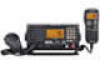
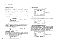
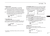
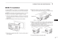
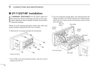
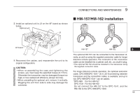
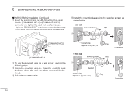
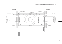
9 CONNECTIONS AND MAINTENANCE ■ MB-75 installation An optional MB-75 FLUSH MOUNT KIT is available for mounting the transceiver to a flat surface such as an instrument panel. KEEP the transceiver and microphone at least 1 m (3.3 ft) away from the vessel's magnetic navigation compass. q Using the attached template, carefully cut a hole into the instrument panel (or wherever you plan to mount the transceiver). w Slide the transceiver into the hole as shown below. e Attach the 2 supplied bolts (M5 × 8 mm) on either side of the IC-M604A. r Attach the clamps on either side of the IC-M604A. • Make sure that the clamps align parallel to the IC-M604A's body. Supplied bolt Clamp 9 t Tighten the end bolts on the clamps (rotate clockwise) so that the clamps press firmly against the inside of the instrument control panel. (Torque: 0.6 N.m) y Tighten the locking nuts (rotate counterclockwise) so that the IC-M604A is securely mounted into position. End bolt y Locking nut t u Connect the antenna and power cable. 53
-
 1
1 -
2
-
3
-
4
-
5
-
6
-
7
-
8
-
9
-
10
-
11
-
12
-
13
-
14
-
15
-
16
-
17
-
18
-
19
-
20
-
21
-
22
-
23
-
24
-
25
-
26
-
27
-
28
-
29
-
30
-
31
-
32
-
33
-
34
-
35
-
36
-
37
-
38
-
39
-
40
-
41
-
42
-
43
-
44
-
45
-
46
-
47
-
48
-
49
-
50
-
51
-
52
-
53
-
 54
54 -
 55
55 -
 56
56 -
 57
57 -
 58
58 -
 59
59 -
 60
60 -
 61
61 -
 62
62 -
 63
63 -
 64
64 -
65
-
66
-
67
-
68
 |
 |