Icom IC-M604A Instruction Manual - Page 65
SPECIFICATIONS AND OPTIONS, ■ Specifi cations
 |
View all Icom IC-M604A manuals
Add to My Manuals
Save this manual to your list of manuals |
Page 65 highlights
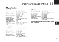
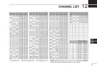
11 SPECIFICATIONS AND OPTIONS ■ Specifications D General • Frequency coverage • Mode • Current drain (at 13.8 V) • Power supply requirement • Frequency stability • Operating temp. range • Antenna impedance • Input impedance (MIC) • Output impedance (audio) • Dimensions (Projections not included) • Weight : TX 156.025-157.425 MHz RX 156.050-163.275 MHz : FM (16K0G3E), DSC (16K0G2B) : TX high (25 W) 5.5 A Max. audio 1.5 A : 13.8 V DC ±15% (negative ground) : ±5 ppm : -20°C to +60°C; -4°F to +140°F : 50 Ω nominal : 2 kΩ : 4 Ω : 220(W) × 110(H) × 109.4(D) mm 8.7(W) × 4.3(H) × 4.3(D) in : Approx. 1400 g; 3.09 lb D Transmitter • RF output power • Modulation system • Max. frequency deviation • Spurious emissions • Adjacent channel power • Audio harmonic distortion • Residual modulation • Audio frequency response : 25 W and 1 W : Variable reactance frequency modulation : ±5.0 kHz : Less than -70 dBc : More than 70 dB : Less than 10% (at 1 kHz, 60% deviation) : More than 40 dB : +1 to -3 dB of 6 dB/octave range from 300 Hz to 3000 Hz D Receiver • Receive system : Double conversion superheterodyne • Sensitivity (12 dB SINAD) : -120 dBm (typical) -120 dBm (typical) (CH 70 receiver) • Squelch sensitivity : Less than -117 dBm • Spurious response : More than 80 dB • Intermodulation : More than 80 dB • Adjacent channel selectivity : More than 80 dB • Hum and noise : More than 40 dB • Audio output power : 5.0 W (typical) at 10% distortion with a 4 Ω load All stated specifications are subject to change without notice or obligation. 10 11 59
-
 1
1 -
2
-
3
-
4
-
5
-
6
-
7
-
8
-
9
-
10
-
11
-
12
-
13
-
14
-
15
-
16
-
17
-
18
-
19
-
20
-
21
-
22
-
23
-
24
-
25
-
26
-
27
-
28
-
29
-
30
-
31
-
32
-
33
-
34
-
35
-
36
-
37
-
38
-
39
-
40
-
41
-
42
-
43
-
44
-
45
-
46
-
47
-
48
-
49
-
50
-
51
-
52
-
53
-
54
-
55
-
56
-
57
-
58
-
59
-
 60
60 -
 61
61 -
 62
62 -
 63
63 -
 64
64 -
 65
65 -
 66
66 -
 67
67 -
 68
68
 |
 |
