Icom IC-PW1 Instruction Manual - Page 10
System interconnections
 |
View all Icom IC-PW1 manuals
Add to My Manuals
Save this manual to your list of manuals |
Page 10 highlights
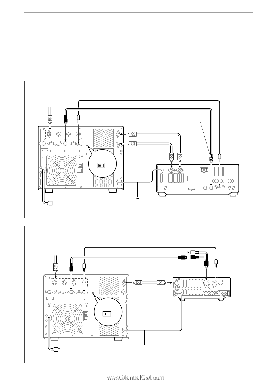
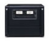
2 INSTALLATION AND CONNECTIONS s System interconnections 1 or 2 Icom 100 W HF transceivers can be connected as exciters to the IC-PW1. Non-Icom transceivers can be used, however, band selection will not be synchronized for each exciter. See the following diagrams for making connections between the IC-PW1 and an exciter (transceiver). See p. 5 for AC power cable connection. • Using 1 Icom exciter (transceiver) To an antenna ACC-1 ANT REMOTE EXCITER 1 1&2 Remote control cable (supplied) ACC cable (supplied) Be sure to connect the cable to the 7-pin ACC(2) jack. INPUT1 Coaxial cable (supplied) INPUT2 Coaxial cable (optional) ANT2 GND Connect [INPUT2] if necessary. ANT1 ACC(2) REMOTE GND IC-PW1 AC outlet (Non-Europe versions : 100-120/220-240 V Europe version : 230 V) Ground IC-756 • Using a 13-pin ACC socket (IC-706 series) To an antenna ACC-1 ANT REMOTE Remote control cable (supplied) OPC-599 (optional) ACC cable (supplied) INPUT1 ANT1 ACC (13 pins) REMOTE Coaxial cable (supplied) EXCITER 1 1&2 GND IC-706 series GND IC-PW1 AC outlet (Non-Europe versions : 100-120/220-240 V Europe version : 230 V) Ground 7
-
 1
1 -
2
-
3
-
4
-
 5
5 -
 6
6 -
 7
7 -
 8
8 -
 9
9 -
 10
10 -
 11
11 -
 12
12 -
 13
13 -
 14
14 -
 15
15 -
16
-
17
-
18
-
19
-
20
 |
 |