Icom IC-PW1 Instruction Manual - Page 7
Dacc-1 Socket Dacc-2 Socket
 |
View all Icom IC-PW1 manuals
Add to My Manuals
Save this manual to your list of manuals |
Page 7 highlights
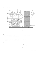
1 PANEL DESCRIPTION !0 EXCITER SELECTOR [EXCITER] (pgs. 7-9) Sets the connected exciter number. - Select [1] when 1 exciter is connected. [ACC-2] outputs the received [ACC-1] signal to another Icom option such as the EX-627 AUTOMATIC ANTENNA SELECTOR. - Select [1&2] when 2 exciters or 1 exciter with 2 specified band antenna connectors is connected. !1 INPUT ANTENNA CONNECTORS [INPUT1]/[INPUT2] (p. 6) Accept a 50 Ω antenna with a PL-259 connector. D ACC-1 SOCKET ACC-1 7 6 3 1 524 Rear panel view PIN NO. PIN NAME DESCRIPTION SPECIFICATIONS 1 8 V Regulated reference 8 V DC input for band control. Input voltage Input current : 8 V ±0.3 V : Less than 10 mA 2 GND Connects to ground. Input/output pin. Ground level : -0.5 V to 0.8 V 3 SEND Goes to ground when transmitting. Output current : Less than 20 mA When grounded, transmits. Input current : Less than 200 mA 4 BAND Band voltage input. (Varies with amateur band) Input voltage : 0 to 8.0 V 5 ALC ALC voltage output. Control voltage : -10 to 0 V Output impedance : 10 kΩ 6 NC No connection. 7 13.8 V 13.8 V DC input terminal. Input current : Less than 1 A D ACC-2 SOCKET (w/[EXCITER] is "1") The following descriptions are applied when the [EXCITER] switch is set to "1" (default). When [EXCITER] is set to "1&2," [ACC-2] functions the same as [ACC-1] above for the 2nd exciter. ACC-2 7 6 3 1 524 Rear panel view PIN NO. PIN NAME DESCRIPTION SPECIFICATIONS 1 8 V Regulated reference 8 V DC output Output voltage from the [ACC-1] socket. Output current : 8 V ±0.3 V : Less than 10 mA 2 GND Connects to ground. Input/output pin. Ground level : -0.5 V to 0.8 V 3 SEND Goes to ground when transmitting. Output current : Less than 20 mA When grounded, transmits. Input current : Less than 200 mA Band voltage output from the 4 BAND [ACC-1] socket. (Varies with amateur band) Output voltage : 0 to 8.0 V 5 ALC ALC voltage output. Control voltage : -10 to 0 V Output impedance : 10 kΩ 6 NC No connection. 7 13.8 V 13.8 V DC output terminal from the [ACC-1] socket. Output current : Less than 1 A 4
-
 1
1 -
 2
2 -
 3
3 -
 4
4 -
 5
5 -
 6
6 -
 7
7 -
 8
8 -
 9
9 -
 10
10 -
 11
11 -
 12
12 -
13
-
14
-
15
-
16
-
17
-
18
-
19
-
20
 |
 |
