Icom IC-PW1 Instruction Manual - Page 11
IC-706 series
 |
View all Icom IC-PW1 manuals
Add to My Manuals
Save this manual to your list of manuals |
Page 11 highlights
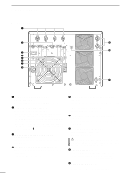
2 INSTALLATION AND CONNECTIONS • Using 2 Icom exciters (transceivers) The following connections also apply to transceivers having multiple antenna connectors for specified bands (e.g. IC-726, IC-729, etc.) To an antenna ACC-1 ANT REMOTE Remote control cable (supplied) OPC-599 (optional) ACC cable (supplied) Coaxial cable (supplied) INPUT1 ANT1 ACC REMOTE ACC-2 REMOTE EXCITER 1 1&2 INPUT2 OPK-5 (optional) GND ANT1 or 2 GND IC-706 series IC-756 GND IC-PW1 Ground AC outlet (Non-Europe versions : 100-120/220-240 V Europe version : 230 V) OPK-5 (optional) ACC(2) OPK-5 (optional) Be sure to connect the cable to the 7-pin ACC(2) jack. REMOTE • Using a non-Icom exciter (transceiver) Set the [EXCITER] switch to [1] when 1 exciter is connected; set to [1&2] when 2 exciters are connected. NOTE: The specifications for the SEND relay are 5 V DC 0.1 A. If this level is exceeded, a large external relay must be used. To an antenna ALC1 ANT SEND1 RCA plug INPUT1 ALC SEND SEND EXCITER 1 1&2 Relay DC power GND Coaxial cable (supplied) IC-PW1 AC outlet (Non-Europe versions : 100-120/220-240 V Europe version : 230 V) Ground RF OUT GND DC OUT SEND ALC Non-Icom exciter 8
-
 1
1 -
2
-
3
-
4
-
5
-
 6
6 -
 7
7 -
 8
8 -
 9
9 -
 10
10 -
 11
11 -
 12
12 -
 13
13 -
 14
14 -
 15
15 -
 16
16 -
17
-
18
-
19
-
20
 |
 |
