Icom IC-R9500 Service Manual - Page 10
Mix1 Unit, Connect-b Unit Af Amplifier Circuits, Scope/tv Unit, Main Unit Audio Demodulation
 |
View all Icom IC-R9500 manuals
Add to My Manuals
Save this manual to your list of manuals |
Page 10 highlights
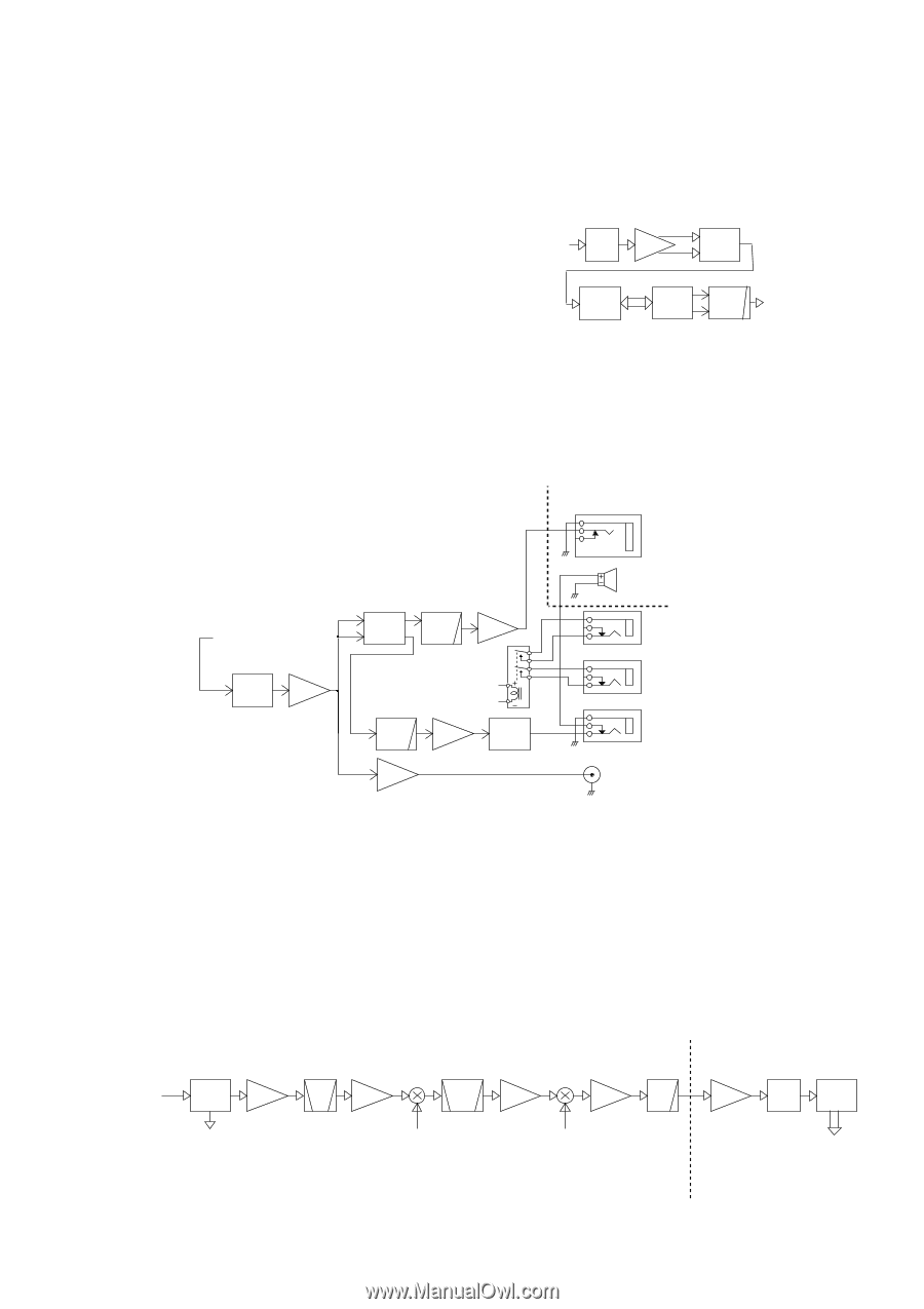
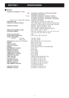
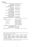
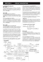
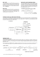
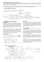
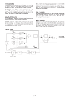
MIX1 UNIT The received signals from the RF-B UNIT are mixed with 1st LO signals from the PLL UNIT, to generate 1st IF signal. The generated 1st IF signal is applied to the RF-B UNIT again, then filtered by 1st IF filter, and amplified by 1st IF amplifier before being applied to the 2nd mixer (MIX2 UNIT; IC21).. (Refer to "MIX2 UNIT") MIX2 UNIT The 1st IF signal from the RF-B UNIT is converted into the 2nd IF signal at 2nd mixer (IC21) by mixing with 2nd LO signal (2LO) from PLL UNIT. The converted 2nd IF signal is applied to the RF-A UNIT. (Refer to "RF-A UNIT ") MAIN UNIT (AUDIO DEMODULATION) The 3rd/4th IF signal from the RF-A UNIT is applied to the A/ D converter (IC1305) via buffer, and converted into the digital audio signal. The converted digital audio signal is applied to the DSP IC (IC1005) and processed. The processed digital audio signal is converted into the analog audio signals at the D/A converter (IC1401), then applied to the AF amplifier of the CONNECT-B UNIT via LPF. • AF DEMODULATOR CIRCUITS (other than WFM) 3rd IF signal from RF-A UNIT IC1302 SW IC1304 + BUFF - IC1305 A/D IC1005 RX DSP IC1401 D/A IC1421 LPF Demodulated analog AF signals to the AFcircuits CONNECT-B UNIT (AF AMPLIFIER CIRCUITS) The AF signals from the MAIN UNIT are applied to the AF amplifier (IC41) via the squelch gate (Q91). The amplified signals are passed through the VCA (Voltage Controlled Attenuator; IC21) for audio output level adjustment. The level adjusted AF signals are output from ext. speaker after being amplified by AF power amplifier (IC11), or output from internal speaker/phones after being power-amplified by AF power amplifier (IC81). • AF CIRCUITS FRONT UNIT Demodulated AF signals from the MAIN UNIT Q91 SQL GATE IC41 AF AMP IC21 VCA Q21 LPF IC81 AF AMP CONNECT-B UNIT RL401 Q22 LPF IC11 PWR AMP AF MUTE Q1 AF AMP IC41 PHONE INTERNAL SP REC REMOTE DET OUT EXT. SP LINE OUT SCOPE/TV UNIT -SPECTRUM SCOPE SCREENA potion of the IF* signal from the RF-A UNIT is passed through the splitter, and, amplified by IF* amplifiers and filtered, then converted into the another IF* signal at the mixer. The converted IF* signal is filtered and amplified by X'tal filter and IF amplifiers, then applied to the mixer to be converted again. The converted IF* signal is amplified and buffer amplified, then applied to the MAIN UNIT via LPF. The IF* signal from the SCOPE/TV UNIT is amplified, and applied to the A/D converter, to be converted to the digital signal. The converted digital signal is applied to the scope DSP IC and processed to convert its data format for spectrum scope screen. • SCOPE CIRCUIT Q1001 1st/2nd IF signal from the RF-A UNIT SPLITTER IF AMP BPF IF signal to the video AM-demodulation circuit Q1051 IF AMP 200kHz=>80dB BW=>30k Q1202 IC1101 Q1203 XTAL IF BPF AMP IC1601 D1701 BUFF 24.2MHz 2nd/3rd LO signal from the OSC UNIT 3rd/4th LO signal from the PLL UNIT IC1602 LPF AMP A/D 200kHz IC2201 IC2051 SCOPE DSP To the MAIN CPU2 (MAIN UNIT; IC604) SCOPE/TV UNIT MAIN UNIT *; 1st IF for 0.005−29.999 MHz signals. 2nd IF for 30−3335 MHz signals. 3 - 2
-
 1
1 -
2
-
3
-
4
-
 5
5 -
 6
6 -
 7
7 -
 8
8 -
 9
9 -
 10
10 -
 11
11 -
 12
12 -
 13
13 -
 14
14 -
 15
15 -
16
-
17
-
18
-
19
-
20
-
21
-
22
-
23
-
24
-
25
-
26
-
27
-
28
-
29
-
30
-
31
-
32
-
33
-
34
-
35
-
36
-
37
-
38
-
39
-
40
-
41
-
42
-
43
-
44
-
45
-
46
-
47
-
48
-
49
-
50
-
51
-
52
-
53
-
54
-
55
-
56
-
57
-
58
-
59
-
60
-
61
-
62
-
63
-
64
-
65
-
66
-
67
-
68
-
69
-
70
-
71
-
72
-
73
-
74
-
75
-
76
-
77
-
78
-
79
-
80
-
81
-
82
-
83
-
84
-
85
-
86
-
87
-
88
-
89
-
90
-
91
-
92
-
93
-
94
-
95
-
96
-
97
-
98
-
99
-
100
-
101
-
102
-
103
-
104
-
105
-
106
-
107
-
108
-
109
-
110
-
111
-
112
-
113
-
114
-
115
-
116
-
117
-
118
-
119
-
120
-
121
-
122
-
123
-
124
-
125
-
126
-
127
-
128
-
129
-
130
-
131
-
132
-
133
-
134
-
135
-
136
-
137
-
138
 |
 |