Icom IC-R9500 Service Manual - Page 12
VCO2 BOARD, DOUBLER BOARD, bipolar TRs Q4100 and Q4101. 20MHz, and 837.4MHz
 |
View all Icom IC-R9500 manuals
Add to My Manuals
Save this manual to your list of manuals |
Page 12 highlights
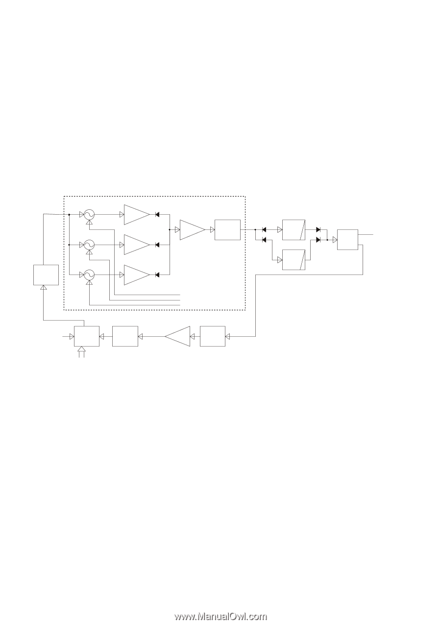
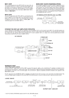
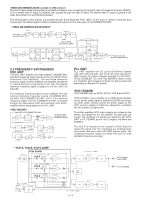
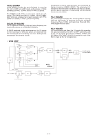
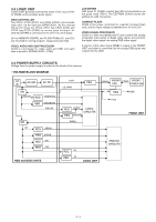
VCO2 BOARD VCO2 BOARD provides the 2nd LO signals for receiving the both of VHF and UHF bands, and contains 3 VCOs oscillating 220 MHz, 720 MHz and 837.4 MHz LO signals. The 220MHz band VCO is a totem pole typed one with bipolar TRs (Q4100 and Q4101). 20MHz, and 837.4MHz band VCOs are employed tank typed resonator with FETs (Q4201 and Q4301) to obtain good C/N capability. DOUBLER BOARD 1st LO signals for receiving 1GHz and below frequency are doubled by doublers on the BOUBLER BOARD. IC-R9500 employed doubler which produces 1st LO signals for the receiving 1.8 GHz and above, and improved the IP3 characteristic and sensitivity, and more, destroyed the necessary of the converter circuits. The doubler circuit is balanced type and composed by bipolar transistors (Q2200, Q2201). The employment of transistors improved lower conversion loss than by diodes, and the same capability of attenuating odd numbered harmonics as by diodes. FIL1 BOARD Fil1 board doubles and filters the 1st LO signals for recieving VHF and UHF bands. To suppress the directly oscillated frequency (Fosc×1) MHz and harmonics (Fosc×N) MHz, three staged filters are used. FIL2 BOARD Fil2 board doubles and filters 2nd LO signals. By expanding the pass band width of the BPF, the BPF commonly used for the 1st LO signals genarated by 220MHz, 720MHz and 837.4MHz VCOs. MMIC (IC4450) is inserted in front of the filter to make up the 1st LO signal level. • VCO2 LOOP 220MHz Q4101 720MHz Q4201 LOOP FIL 837.4MHz Q4301 Ref 200kHz IC4000 Ref 500kHz PLL IC Q4100 BUFF Q4200 BUFF Q4400 BUFF ATT Q4300 BUFF L21V L22V L23V VCO2 BOARD IC4501 ATT AM P ATT LPF 2nd LO signals 6dB to FIL2 BOARD HYB LPF DATA/CK/PST2P 3 - 4
-
 1
1 -
2
-
3
-
4
-
5
-
6
-
 7
7 -
 8
8 -
 9
9 -
 10
10 -
 11
11 -
 12
12 -
 13
13 -
 14
14 -
 15
15 -
 16
16 -
 17
17 -
18
-
19
-
20
-
21
-
22
-
23
-
24
-
25
-
26
-
27
-
28
-
29
-
30
-
31
-
32
-
33
-
34
-
35
-
36
-
37
-
38
-
39
-
40
-
41
-
42
-
43
-
44
-
45
-
46
-
47
-
48
-
49
-
50
-
51
-
52
-
53
-
54
-
55
-
56
-
57
-
58
-
59
-
60
-
61
-
62
-
63
-
64
-
65
-
66
-
67
-
68
-
69
-
70
-
71
-
72
-
73
-
74
-
75
-
76
-
77
-
78
-
79
-
80
-
81
-
82
-
83
-
84
-
85
-
86
-
87
-
88
-
89
-
90
-
91
-
92
-
93
-
94
-
95
-
96
-
97
-
98
-
99
-
100
-
101
-
102
-
103
-
104
-
105
-
106
-
107
-
108
-
109
-
110
-
111
-
112
-
113
-
114
-
115
-
116
-
117
-
118
-
119
-
120
-
121
-
122
-
123
-
124
-
125
-
126
-
127
-
128
-
129
-
130
-
131
-
132
-
133
-
134
-
135
-
136
-
137
-
138
 |
 |