Icom IC-R9500 Service Manual - Page 18
Adjustment Procedures, Preparation, Ic-r9500
 |
View all Icom IC-R9500 manuals
Add to My Manuals
Save this manual to your list of manuals |
Page 18 highlights
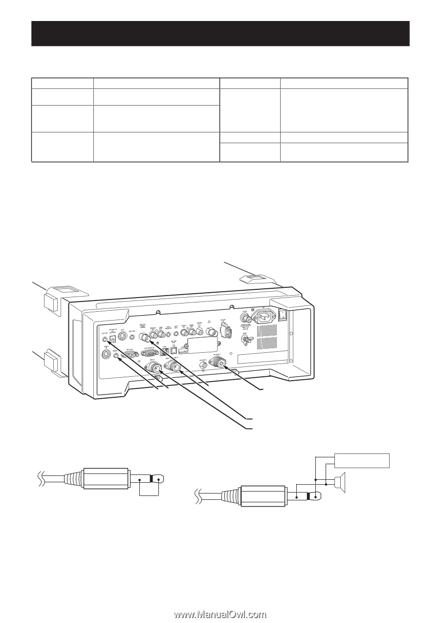
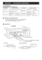
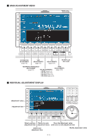
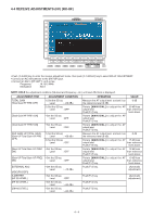
SECTION 4 ADJUSTMENT PROCEDURE 4-1 PREPARATION ¤ REQUIRED TEST EQUIPMENTS EQUIPMENT GRADE AND RANGE DC voltmeter Input impedance : 50 kΩ /V DC or better RF Milliwatt meter Measuring range : 0.5-5 dBm Input impedance : 50 Ω Frequency range : 0.1-300 MHz Frequency counter Frequency accuracy: ±1 ppm or better Sensitivity : 100 mV or better EQUIPMENT Standard signal generator (SG) AC millivoltmeter External speaker GRADE AND RANGE Frequency range : 0.1-3.5 GHz Output level : 0.1 µV to 32 mV (-127 to -17 dBm) Output impedance : 50 Ω Modulation : None Measuring range : 10 mV to 10 V Input impedance : 8 Ω Capacity : More than 5 W ¤ ENTERING ADJUSTMENT MODE q Connect the short plug (see the iluustlation below) to the [REMOTE] jack. w Push and hold [FM] and [WFM] keys then turn the power ON. e The main adjustment menu will appear as next page. ¤ CONNECTION IC-R9500 ShorEt xptleurgnal speaker Freq. plug Counter SG (for adjustment [HF] ) SG (for adjustments [V/U], [V/U1], [TV] and [WFM]) SG (for adjustment [V/U2]) • Short plug 3.5 mm (1/8'' ) monoral plug (Short) • External speaker plug 3.5 mm (1/8'' ) monoral plug + AC millivolt meter − + − Speaker (8 Ω) 4 - 1
-
 1
1 -
2
-
3
-
4
-
5
-
6
-
7
-
8
-
9
-
10
-
11
-
12
-
 13
13 -
 14
14 -
 15
15 -
 16
16 -
 17
17 -
 18
18 -
 19
19 -
 20
20 -
 21
21 -
 22
22 -
 23
23 -
24
-
25
-
26
-
27
-
28
-
29
-
30
-
31
-
32
-
33
-
34
-
35
-
36
-
37
-
38
-
39
-
40
-
41
-
42
-
43
-
44
-
45
-
46
-
47
-
48
-
49
-
50
-
51
-
52
-
53
-
54
-
55
-
56
-
57
-
58
-
59
-
60
-
61
-
62
-
63
-
64
-
65
-
66
-
67
-
68
-
69
-
70
-
71
-
72
-
73
-
74
-
75
-
76
-
77
-
78
-
79
-
80
-
81
-
82
-
83
-
84
-
85
-
86
-
87
-
88
-
89
-
90
-
91
-
92
-
93
-
94
-
95
-
96
-
97
-
98
-
99
-
100
-
101
-
102
-
103
-
104
-
105
-
106
-
107
-
108
-
109
-
110
-
111
-
112
-
113
-
114
-
115
-
116
-
117
-
118
-
119
-
120
-
121
-
122
-
123
-
124
-
125
-
126
-
127
-
128
-
129
-
130
-
131
-
132
-
133
-
134
-
135
-
136
-
137
-
138
 |
 |