Icom IC-R9500 Service Manual - Page 9
Circuit Description, Receive Circuits, Bpf Unit, Ant Unit, Rf-a Unit
 |
View all Icom IC-R9500 manuals
Add to My Manuals
Save this manual to your list of manuals |
Page 9 highlights
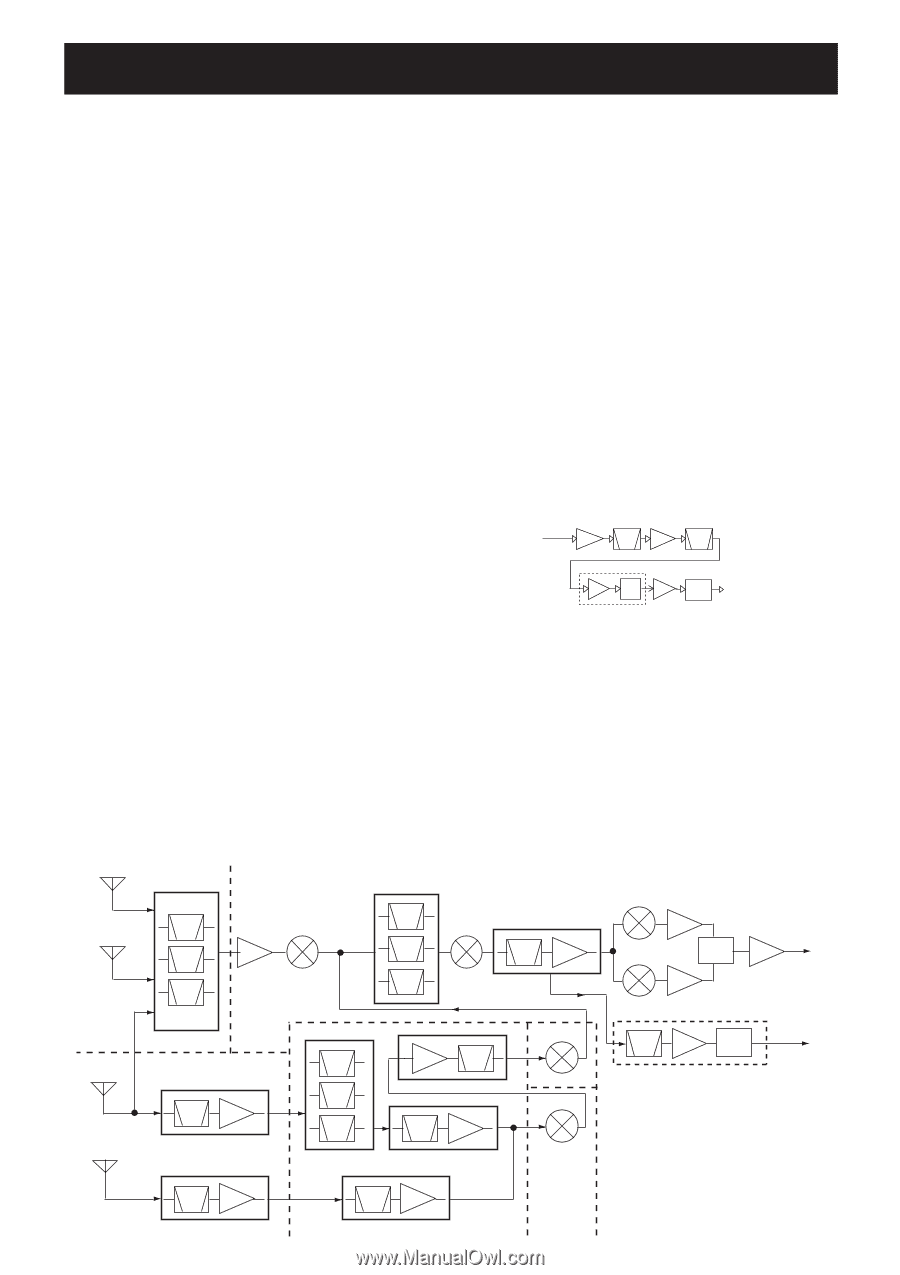
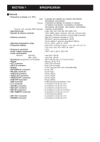
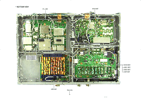
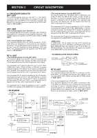
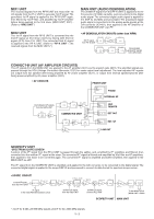
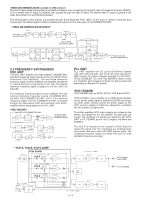
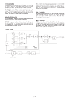
SECTION 3 CIRCUIT DESCRIPTION 3-1 RECEIVER CIRCUITS BPF UNIT The received signals from the "HF ANT1" or "HF ANT2" connector (0.005−29.999 MHz) are passed through the attenuators and each BPFs for the frequency coverage. The filtered The received signals are applied to the RF-A UNIT (Refer to "RF-A UNIT"). ANT UNIT The received signals from the ANT1 connector (30−1150 MHz) are amplified or attenuated by pre-amplifier/attenuator. The amplified signals are applied to the RF-B UNIT (Refer to "RF-B UNIT"). The received signals from the ANT2 connector (1150− 3335 MHz) are amplified or attenuated by pre-amplifier/ attenuator. The amplified/attenuated signals are amplified by one or two RF amplifiers via band switches, LPFs and HPFs. The amplified signals are applied to the RF-B UNIT. (Refer to "RF-B UNIT") The 2nd IF signal from the MIX2 UNIT is filtered by one of 2nd IF filters (for BW=3 kHz, 6 kHz, 15 kHz, 50 kHz or 240 kHz) to remove unwanted signals. The filtered 2nd IF signal is amplified by 2nd IF amplifier, then applied to the 3rd mixer, and mixed with 3rd LO signals from the PLL UNIT to generate 3rd IF signal. The generated 3rd IF signal is amplified by 3rd IF amplifier, and passed through the 3rd IF filter (BW=50kHz) to remove unwanted signals. The filtered 3rd IF signal is applied to the 4th mixers (D1250 and D1251), and mixed with 4th LO signals from the PLL UNIT to generate 4th IF signal. The generated 4th IF signal is amplified by 4th IF amplifiers, then applied to the MAIN UNIT for demodulation. In WFM mode, the IF signal from the 3rd IF amplifier is amplified by two 3rd IF amplifiers, and filtered by two 3rd IF filters (BW=230 kHz), then applied to the IF IC (IC1031) for FM-demodulation. The demodulated AF signals are applied to the MAIN UNIT via AF switch (IC1312). RF-A UNIT The received signals from the BPF UNIT are amplified and filtered, then applied to the 1st mixer (IC130), and mixed with 1st LO signals from the PLL UNIT to generate 1st IF signal. The generated 1st IF signal is filtered by one of 1st IF filters ( BW=3 kHz, 6 kHz, 15 kHz, 50 kHz or 240 kHz) to remove unwanted signals. The filtered 1st IF signal is amplified by 1st IF amplifier, then applied to the 2nd mixer and mixed with 2nd LO signals from the PLL UNIT to generate 2nd IF signal. The generated 2nd IF signal is amplified by 2nd IF amplifier, and passed through the 2nd IF filter (BW=50kHz) to remove unwanted signals. The filtered 2nd IF signal is applied to the 3rd mixers (D1250 and D1251), and mixed with 3rd LO signals from the PLL UNIT to generate 3rd IF signal. The generated 3rd IF signal is amplified by 3rd IF amplifier (IC1000), then applied to the MAIN UNIT for demodulation. • RX DIAGRAM HF ANT1 0.005-29.999 MHz BPF UNIT • AF DEMODULATOR CIRCUITS (WFM) Q1011 3rd IF signal IF AMP from the 3rd IF amp. BW=230K CERAMIC BPF Q1021 IF AMP BW=230K CERAMIC BPF IC1031 IF WFM AMP DET IC1030 BUFF IC1312 SELECT SW AF signals to the MAIN UNIT RF-B UNIT The received signals from the ANT-2 connector (1150− 3335 MHz) are amplified and filtered, then applied to the 1st mixer (MIX1 UNIT; IC301) via band SW (IC1202). (Refer to "MIX1 UNIT") The received signals from the ANT-1 connector (30− 1150 MHz) are filtered by one of BPFs for the frequency coverage to remove unwanted signals. The filtered The received signals are amplified by RF amplifiers, filtered by band filters, then applied to the 1st mixer (MIX1 UNIT; IC301) via band switch (IC1202). (Refer to "MIX1 UNIT") HF ANT2 0.005-29.999 MHz BPF BPF BPF amp. IC130 RF-A UNIT ANT1 0.005- 30-1150 MHz 29.999 MHz ANT UNIT ANT2 1150- 3335 MHz BPF amp. BPF BPF BPF BPF D600 BPF BPF amp. BPF BPF amp. BPF amp. IC21 MIX2 UNIT IC301 MIX1 UNIT D1250 amp. 3rd IF signal to the MAIN UNIT D1251 90° amp. amp. WFM DEMODULATION BPF amp. WFM Det. AF signal to the MAIN UNIT BPF amp. BPF amp. RF-B UNIT 3 - 1
-
 1
1 -
2
-
3
-
 4
4 -
 5
5 -
 6
6 -
 7
7 -
 8
8 -
 9
9 -
 10
10 -
 11
11 -
 12
12 -
 13
13 -
 14
14 -
15
-
16
-
17
-
18
-
19
-
20
-
21
-
22
-
23
-
24
-
25
-
26
-
27
-
28
-
29
-
30
-
31
-
32
-
33
-
34
-
35
-
36
-
37
-
38
-
39
-
40
-
41
-
42
-
43
-
44
-
45
-
46
-
47
-
48
-
49
-
50
-
51
-
52
-
53
-
54
-
55
-
56
-
57
-
58
-
59
-
60
-
61
-
62
-
63
-
64
-
65
-
66
-
67
-
68
-
69
-
70
-
71
-
72
-
73
-
74
-
75
-
76
-
77
-
78
-
79
-
80
-
81
-
82
-
83
-
84
-
85
-
86
-
87
-
88
-
89
-
90
-
91
-
92
-
93
-
94
-
95
-
96
-
97
-
98
-
99
-
100
-
101
-
102
-
103
-
104
-
105
-
106
-
107
-
108
-
109
-
110
-
111
-
112
-
113
-
114
-
115
-
116
-
117
-
118
-
119
-
120
-
121
-
122
-
123
-
124
-
125
-
126
-
127
-
128
-
129
-
130
-
131
-
132
-
133
-
134
-
135
-
136
-
137
-
138
 |
 |