Icom IC-R9500 Service Manual - Page 2
Introduction, Ic-r9500, Never, Do Not, Model, Version, Frequency Coverage Mhz, <sample Order> - communications receiver
 |
View all Icom IC-R9500 manuals
Add to My Manuals
Save this manual to your list of manuals |
Page 2 highlights
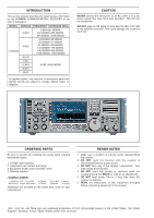
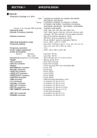
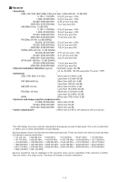
INTRODUCTION This service manual describes the latest service information for the IC-R9500 COMMUNICATIONS RECEIVER at the time of publication. MODEL VERSION FREQUENCY COVERAGE (MHz) [USA] 0.005-821.999999, 851.000000-866.999999, 896.000000-3335.000000 IC-R9500 [FRA] 0.0050000-29.999999, 50.200000-51.200000, 87.500000-108.000000, 144.000000-146.000000, 430.000000-440.000000, 1240.000000-1300.000000 [EUR] [UK] [CAN] 0.005-3335.000000 [EXP] [AUS] To upgrade quality any electrical or mechanical parts and internal circuits are subject to change without notice or obligation. CAUTION NEVER connect the transceiver to an AC outlet or to a DC power supply that uses more than specified. This will ruin the transceiver. DO NOT apply an RF signal of more than 20 dBm (100 mW) to the antenna connector. This could damage the receiver's front end. ORDERING PARTS Be sure to include the following four points when ordering replacement parts: 1. 10-digit order numbers 2. Component part number and name 3. Equipment model name and UNIT name 4. Quantity required 1110006750 S.IC TK14570L IC-R9500 8820001210 Screw 2844 screw IC-R9500 RF-A UNIT 5 pieces CHASSIS 10 pieces Addresses are provided on the inside back cover for your convenience. REPAIR NOTES 1. Make sure a problem is internal before disassembling the receiver. 2. DO NOT open the receiver until the receiver is disconnected from its power source. 3. DO NOT force any of the variable components. Turn them slowly and smoothly. 4. DO NOT short any circuits or electronic parts. An insulated tuning tool MUST be used for all adjustments. 5. DO NOT keep power ON for a long time when the receiver is defective. 6. READ the instructions of test equipment throughly before connecting equipment to the receiver. Icom Icom Inc. and logo are registered trademarks of Icom Incorporated (Japan) in the United States the United Kingdom Germany France Spain Russia and/or other countries.
-
 1
1 -
 2
2 -
 3
3 -
 4
4 -
 5
5 -
 6
6 -
 7
7 -
 8
8 -
9
-
10
-
11
-
12
-
13
-
14
-
15
-
16
-
17
-
18
-
19
-
20
-
21
-
22
-
23
-
24
-
25
-
26
-
27
-
28
-
29
-
30
-
31
-
32
-
33
-
34
-
35
-
36
-
37
-
38
-
39
-
40
-
41
-
42
-
43
-
44
-
45
-
46
-
47
-
48
-
49
-
50
-
51
-
52
-
53
-
54
-
55
-
56
-
57
-
58
-
59
-
60
-
61
-
62
-
63
-
64
-
65
-
66
-
67
-
68
-
69
-
70
-
71
-
72
-
73
-
74
-
75
-
76
-
77
-
78
-
79
-
80
-
81
-
82
-
83
-
84
-
85
-
86
-
87
-
88
-
89
-
90
-
91
-
92
-
93
-
94
-
95
-
96
-
97
-
98
-
99
-
100
-
101
-
102
-
103
-
104
-
105
-
106
-
107
-
108
-
109
-
110
-
111
-
112
-
113
-
114
-
115
-
116
-
117
-
118
-
119
-
120
-
121
-
122
-
123
-
124
-
125
-
126
-
127
-
128
-
129
-
130
-
131
-
132
-
133
-
134
-
135
-
136
-
137
-
138
 |
 |