Intel D845HV Product Guide - Page 11
Processor, Main Memory, Up to three 168-pin SDRAM Dual Inline Memory Modules DIMMs with gold-plated - board
 |
View all Intel D845HV manuals
Add to My Manuals
Save this manual to your list of manuals |
Page 11 highlights
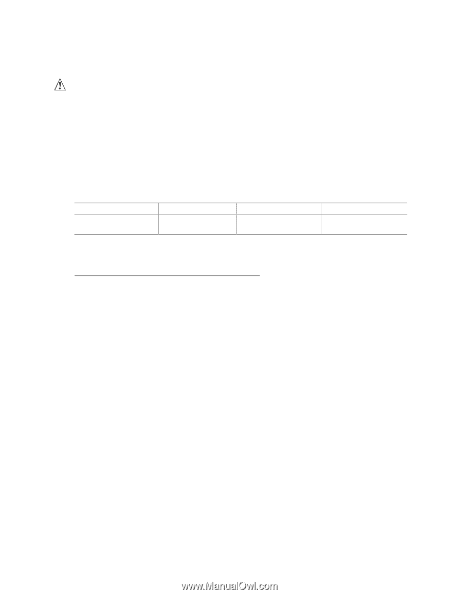
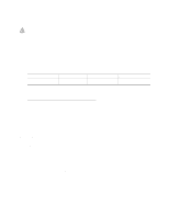
Desktop Board Features Processor CAUTION Failure to use an ATX12V power supply, or not connecting the additional power supply lead to the D845HV or D845WN boards may result in damage to the desktop board and/or power supply. The boards support a single Intel Pentium 4 processor. Processors are not included with the board and must be purchased separately. The processor connects to the board through the mPGA 478-pin socket. The Intel Pentium 4 processor may be removed and replaced to accommodate supported higher speed processors. The board supports the processors listed in Table 2. Table 2. Processors Supported by the Desktop Board Type Designation System Bus Frequency Intel Pentium 4 processor 1.4, 1.5, 1.6, 1.7, and in an mPGA-478 package 1.8 GHz 400 MHz L2 Cache Size 256 KB For the latest information on processor support for the D845HV and D845WN boards, refer to the Intel World Wide Web site at: http://support.intel.com/support/motherboards/desktop/ For instructions on installing or upgrading the processor, see Chapter 2 on page 21. The D845HV and D845WN boards require an ATX12V compliant power supply to function according to desktop board specifications. Both boards have two ATX12V compliant power supply connectors that are needed to provide extra power to the Intel 845 chipset and Intel Pentium 4 processor. Items A and E in Figure 21 on page 70 show the two power connector locations. Main Memory ✏ NOTE To be fully compliant with all applicable Intel® SDRAM memory specifications, the board should be populated with DIMMs that support the Serial Presence Detect (SPD) data structure. If your memory modules do not support SPD, you will see a notification to this effect on the screen at power up. The BIOS will attempt to configure the memory controller for normal operation. The boards supports system memory as defined below: • Up to three 168-pin SDRAM Dual Inline Memory Modules (DIMMs) with gold-plated contacts • PC133 SDRAM only 11
-
 1
1 -
2
-
3
-
4
-
5
-
 6
6 -
 7
7 -
 8
8 -
 9
9 -
 10
10 -
 11
11 -
 12
12 -
 13
13 -
 14
14 -
 15
15 -
 16
16 -
17
-
18
-
19
-
20
-
21
-
22
-
23
-
24
-
25
-
26
-
27
-
28
-
29
-
30
-
31
-
32
-
33
-
34
-
35
-
36
-
37
-
38
-
39
-
40
-
41
-
42
-
43
-
44
-
45
-
46
-
47
-
48
-
49
-
50
-
51
-
52
-
53
-
54
-
55
-
56
-
57
-
58
-
59
-
60
-
61
-
62
-
63
-
64
-
65
-
66
-
67
-
68
-
69
-
70
-
71
-
72
-
73
-
74
-
75
-
76
-
77
-
78
-
79
-
80
-
81
-
82
-
83
-
84
-
85
-
86
-
87
 |
 |