Intel D865GSA Product Specification - Page 7

s, Tables - processor support

Page 7 highlights

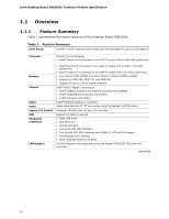
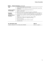
Contents Figures 1. Major Board Components 12 2. Block Diagram 14 3. Memory Channel Configuration 18 4. Example of Dual Channel Configuration with Dynamic Mode 19 5. Example of Single Channel Configuration with Dynamic Mode 19 6. Example of Single Channel Configuration without Dynamic Mode 20 7. LAN Connector LED Locations 38 8. Thermal Sensors and Fan Connectors 40 9. Location of the Standby Power Indicator LED 46 10. Back Panel Connectors 53 11. Component-side Connectors 54 12. Connection Diagram for Front Panel Connector 59 13. Connection Diagram for Front Panel USB Connectors 60 14. Location of the Jumper Block 61 15. Board Dimensions 62 16. I/O Shield Dimensions 63 17. Processor Heatsink for Omni-directional Airflow 66 18. Localized High Temperature Zones 67 Tables 1. Feature Summary 10 2. Board Components Shown in Figure 1 13 3. Supported System Bus Frequency and Memory Speed Combinations 16 4. Supported Memory Configurations 17 5. Characteristics of Dual/Single Channel Configuration with/without Dynamic Mode 18 6. Direct Draw Supported Modes 22 7. Video BIOS Video Modes Supported for Analog CRTs 23 8. Supported Modes for DDR400/DDR333 Dual Channel Configuration 24 9. Supported Modes for DDR266 Dual Channel and DDR333/DDR400 Single Channel Configurations 25 10. Supported Modes for DDR266 Single Channel Configuration 26 11. LAN Connector LED States 38 12. Effects of Pressing the Power Switch 41 13. Power States and Targeted System Power 42 14. Wake-up Devices and Events 43 15. System Memory Map 47 16. I/O Map ...48 17. PCI Configuration Space Map 49 18. Interrupts 50 19. DMA Channels 51 20. PCI Interrupt Routing Map 52 21. Component-side Connectors Shown in Figure 11 55 22. Front and Rear Chassis Fan Connectors 56 23. Processor Fan Connector 56 24. Chassis Intrusion Connector 56 25. Serial ATA Connectors 56 26. ATAPI CD-ROM Connector 56 27. Front Panel Audio Connector 57 vii

  • 1
  • 2
  • 3
  • 4
  • 5
  • 6
  • 7
  • 8
  • 9
  • 10
  • 11
  • 12
  • 13
  • 14
  • 15
  • 16
  • 17
  • 18
  • 19
  • 20
  • 21
  • 22
  • 23
  • 24
  • 25
  • 26
  • 27
  • 28
  • 29
  • 30
  • 31
  • 32
  • 33
  • 34
  • 35
  • 36
  • 37
  • 38
  • 39
  • 40
  • 41
  • 42
  • 43
  • 44
  • 45
  • 46
  • 47
  • 48
  • 49
  • 50
  • 51
  • 52
  • 53
  • 54
  • 55
  • 56
  • 57
  • 58
  • 59
  • 60
  • 61
  • 62
  • 63
  • 64
  • 65
  • 66
  • 67
  • 68
  • 69
  • 70
  • 71
  • 72
  • 73
  • 74
  • 75
  • 76
  • 77
  • 78
  • 79
  • 80
  • 81
  • 82
  • 83
  • 84
  • 85
  • 86
  • 87
  • 88
  • 89
  • 90
  • 91
  • 92
  • 93
  • 94

Contents
vii
Figures
1.
Major Board Components
.............................................................................
12
2.
Block Diagram
............................................................................................
14
3.
Memory Channel Configuration
.....................................................................
18
4.
Example of Dual Channel Configuration with Dynamic Mode
.............................
19
5.
Example of Single Channel Configuration with Dynamic Mode
...........................
19
6.
Example of Single Channel Configuration without Dynamic Mode
.......................
20
7.
LAN Connector LED Locations
.......................................................................
38
8.
Thermal Sensors and Fan Connectors
............................................................
40
9.
Location of the Standby Power Indicator LED
..................................................
46
10. Back Panel Connectors
................................................................................
53
11. Component-side Connectors
.........................................................................
54
12.
Connection Diagram for Front Panel Connector
...............................................
59
13.
Connection Diagram for Front Panel USB Connectors
.......................................
60
14.
Location of the Jumper Block
........................................................................
61
15. Board Dimensions
.......................................................................................
62
16. I/O Shield Dimensions
.................................................................................
63
17.
Processor Heatsink for Omni-directional Airflow
...............................................
66
18. Localized High Temperature Zones
................................................................
67
Tables
1.
Feature Summary
.......................................................................................
10
2.
Board Components Shown in Figure 1
...........................................................
13
3.
Supported System Bus Frequency and Memory Speed Combinations
..................
16
4.
Supported Memory Configurations
................................................................
17
5.
Characteristics of Dual/Single Channel Configuration with/without
Dynamic Mode
...........................................................................................
18
6.
Direct Draw Supported Modes
......................................................................
22
7.
Video BIOS Video Modes Supported for Analog CRTs
.......................................
23
8.
Supported Modes for DDR400/DDR333 Dual Channel Configuration
...................
24
9.
Supported Modes for DDR266 Dual Channel and DDR333/DDR400 Single
Channel Configurations
...............................................................................
25
10.
Supported Modes for DDR266 Single Channel Configuration
..............................
26
11.
LAN Connector LED States
...........................................................................
38
12.
Effects of Pressing the Power Switch
.............................................................
41
13.
Power States and Targeted System Power
......................................................
42
14.
Wake-up Devices and Events
.......................................................................
43
15.
System Memory Map
...................................................................................
47
16.
I/O Map
....................................................................................................
48
17.
PCI Configuration Space Map
.......................................................................
49
18.
Interrupts
..................................................................................................
50
19.
DMA Channels
............................................................................................
51
20.
PCI Interrupt Routing Map
...........................................................................
52
21.
Component-side Connectors Shown in Figure 11
.............................................
55
22.
Front and Rear Chassis Fan Connectors
.........................................................
56
23.
Processor Fan Connector
.............................................................................
56
24.
Chassis Intrusion Connector
.........................................................................
56
25.
Serial ATA Connectors
.................................................................................
56
26.
ATAPI CD-ROM Connector
............................................................................
56
27.
Front Panel Audio Connector
........................................................................
57