Intel D865GSA Product Specification - Page 86
Port 80h POST Codes - problems
 |
View all Intel D865GSA manuals
Add to My Manuals
Save this manual to your list of manuals |
Page 86 highlights
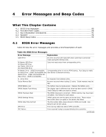
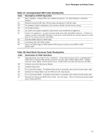
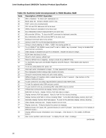
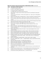
Intel Desktop Board D865GSA Technical Product Specification Table 46. BIOS Error Messages (continued) Error Message Explanation HDC Failure Checking NVRAM..... Update OK! Error occurred trying to access hard disk controller. NVRAM is being checked to see if it is valid. NVRAM was invalid and has been updated. Updated Failed NVRAM was invalid but was unable to be updated. Keyboard Error Error in the keyboard connection. Make sure keyboard is connected properly. KB/Interface Error Keyboard interface test failed. Memory Size Decreased Memory size has decreased since the last boot. If no memory was removed then memory may be bad. Memory Size Increased Memory Size Changed Memory size has increased since the last boot. If no memory was added there may be a problem with the system. Memory size has changed since the last boot. If no memory was added or removed then memory may be bad. No Boot Device Available System did not find a device to boot. Off Board Parity Error On Board Parity Error A parity error occurred on an off-board card. This error is followed by an address. A parity error occurred in onboard memory. This error is followed by an address. Parity Error A parity error occurred in onboard memory at an unknown address. NVRAM/CMOS/PASSWORD cleared by Jumper NVRAM, CMOS, and passwords have been cleared. The system should be powered down and the jumper removed. Pressed CMOS is ignored and NVRAM is cleared. User must enter Setup. 4.2 Port 80h POST Codes During the POST, the BIOS generates diagnostic progress codes (POST-codes) to I/O port 80h. If the POST fails, execution stops and the last POST code generated is left at port 80h. This code is useful for determining the point where an error occurred. Displaying the POST-codes requires a PCI bus add-in card, often called a POST card. The POST card can decode the port and display the contents on a medium such as a seven-segment display. NOTE The POST card must be installed in PCI bus connector 1. The tables below offer descriptions of the POST codes generated by the BIOS. Table 47 defines the uncompressed INIT code checkpoints, Table 48 describes the boot block recovery code checkpoints, and Table 49 lists the runtime code uncompressed in F000 shadow RAM. Some codes are repeated in the tables because that code applies to more than one operation. 86
-
 1
1 -
2
-
3
-
4
-
5
-
6
-
7
-
8
-
9
-
10
-
11
-
12
-
13
-
14
-
15
-
16
-
17
-
18
-
19
-
20
-
21
-
22
-
23
-
24
-
25
-
26
-
27
-
28
-
29
-
30
-
31
-
32
-
33
-
34
-
35
-
36
-
37
-
38
-
39
-
40
-
41
-
42
-
43
-
44
-
45
-
46
-
47
-
48
-
49
-
50
-
51
-
52
-
53
-
54
-
55
-
56
-
57
-
58
-
59
-
60
-
61
-
62
-
63
-
64
-
65
-
66
-
67
-
68
-
69
-
70
-
71
-
72
-
73
-
74
-
75
-
76
-
77
-
78
-
79
-
80
-
 81
81 -
 82
82 -
 83
83 -
 84
84 -
 85
85 -
 86
86 -
 87
87 -
 88
88 -
 89
89 -
 90
90 -
 91
91 -
92
-
93
-
94
 |
 |