Intel DZ68BC Product Guide
Intel DZ68BC Manual
 |
View all Intel DZ68BC manuals
Add to My Manuals
Save this manual to your list of manuals |
Intel DZ68BC manual content summary:
- Intel DZ68BC | Product Guide - Page 1
Intel® Desktop Board DZ68BC Product Guide Order Number: G41105-003 - Intel DZ68BC | Product Guide - Page 2
First release of the Intel® Desktop Board DZ68BC Product Guide Second release of the Intel® Desktop Board DZ68BC Product Guide Third release of the Intel® Desktop Board DZ68BC Product Guide Date August 2011 September 2011 March 2012 Disclaimer INFORMATION IN THIS DOCUMENT IS PROVIDED IN CONNECTION - Intel DZ68BC | Product Guide - Page 3
features 2 Installing and Replacing Desktop Board Components: instructions on how to install the Desktop Board and other hardware components 3 Updating the BIOS: instructions on how to update the BIOS A Error Messages and Indicators: information about BIOS error messages and beep codes B Regulatory - Intel DZ68BC | Product Guide - Page 4
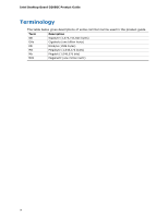
Intel Desktop Board DZ68BC Product Guide Terminology The table below gives descriptions of some common terms used in the product guide. Term Description GB Gigabyte (1,073,741,824 bytes) GHz Gigahertz (one billion hertz) KB Kilobyte (1024 bytes) MB Megabyte (1,048,576 bytes) Mb Megabit - Intel DZ68BC | Product Guide - Page 5
Desktop Board Components 12 Processor ...14 Main Memory...15 Intel® Z68 Express Chipset 16 Intel® Rapid Storage Technology 16 Intel® Smart Response Technology 16 Audio Subsystem 16 LAN Subsystem 17 USB Support ...18 SATA Support...18 SATA RAID 19 Legacy I/O ...19 Expandability...19 Bluetooth - Intel DZ68BC | Product Guide - Page 6
56 Connecting Power Supply Cables 57 Setting the BIOS Configuration Jumper 58 Clearing Passwords 59 Replacing the Battery 60 Installing the WiFi/Bluetooth* Module in a Desktop Chassis (Optional 66 3 Updating the BIOS Updating the BIOS with the Intel® Express BIOS Update Utility 67 Updating the - Intel DZ68BC | Product Guide - Page 7
Back to BIOS Button 22 4. Location of the Standby Power Indicator 26 5. Onboard Power and Reset Buttons 27 6. Location of the Diagnostic LEDs 29 7. Installing the I/O Shield 33 8. Intel Desktop Board DZ68BC Mounting Screw Hole Locations 34 9. Unlatch the Processor Socket Lever 35 10. Lift the - Intel DZ68BC | Product Guide - Page 8
Desktop Board DZ68BC Product Guide 25. Back Panel Audio Connectors 55 26. Location of the Chassis Fan Headers 56 27. Connecting Power Supply Cables 57 28. Location of the BIOS Configuration Jumper Block 58 29. Removing the Battery 65 30. Installing the WiFi/Bluetooth Module 66 31. POST Code - Intel DZ68BC | Product Guide - Page 9
features of Intel® Desktop Board DZ68BC. Table 1 summarizes the major features of the Desktop Board. Table 1. Feature Summary Form Factor Processor Main Memory Chipset ATX (304.80 millimeters [12.00 inches] x 243.84 millimeters [9.60 inches]) Support for an Intel® processor in the LGA1155 package - Intel DZ68BC | Product Guide - Page 10
interface • 32 Mb symmetrical flash memory device • Support for SMBIOS • Intel® Express BIOS Update • Support for Advanced Configuration and Power Interface (ACPI) • Suspend to RAM (STR) • Wake on USB, PCI, PCI Express, LAN, CIR, serial port, and front panel • ENERGY STAR* capable Hardware and - Intel DZ68BC | Product Guide - Page 11
Desktop Board Features Supported Operating Systems The Desktop Board provides full support for the following operating systems: • Microsoft Windows* 7 Ultimate 64-bit edition • Microsoft Windows 7 Ultimate 32-bit edition • Microsoft Windows 7 Professional 64-bit edition • Microsoft Windows 7 - Intel DZ68BC | Product Guide - Page 12
Intel Desktop Board DZ68BC Product Guide Desktop Board Components Figure 1 shows the approximate location of the major components on Intel Desktop Board DZ68BC. Figure 1. Intel Desktop Board DZ68BC Components 12 - Intel DZ68BC | Product Guide - Page 13
front panel power LED header BB Intel Z68 PCH CC Battery DD Two 6.0 Gb/s SATA ports (Marvell controller) EE Two 6.0 Gb/s SATA ports (Intel Z68 PCH) FF Four 3.0 Gb/s SATA ports (Intel Z68 PCH) GG Serial port header HH USB 2.0 headers II BIOS configuration jumper block JJ POST code - Intel DZ68BC | Product Guide - Page 14
/desktop/chipsets/inde x.htm • BIOS and driver updates http://downloadcenter.intel.com/ • Integration information http://www.intel.com/support/go/buildit Processor CAUTION Failure to use an appropriate power supply and/or not connecting the 12 V (2 x 4 pin) power connector to the Desktop Board - Intel DZ68BC | Product Guide - Page 15
with all applicable Intel ® SDRAM memory specifications, the board should be populated with DIMMs that support the Serial Presence Detect (SPD) data structure. If your memory modules do not support SPD, you will see a notification to this effect on the screen at power up. The BIOS will attempt to - Intel DZ68BC | Product Guide - Page 16
Intel Desktop Board DZ68BC Product Guide Intel® Z68 Express Chipset The Intel Z68 Express Chipset consists of the Intel Z68 PCH. The Intel Z68 PCH includes Intel Rapid Storage Technology and Intel Smart Response Technology. Intel® Rapid Storage Technology Intel Rapid Storage Technology version 10.6 - Intel DZ68BC | Product Guide - Page 17
Desktop Board Features The audio subsystem supports the following features: • A signal-to-noise (S/N) ratio of 97 dB • Independent multi-streaming 8-channel (7.1) audio (using the back panel audio connectors) and 2-channel audio (using the Intel HD Audio front panel header) Table 3 lists the - Intel DZ68BC | Product Guide - Page 18
ports are backward compatible with USB 2.0 and USB 1.1 devices. The USB 3.0 ports are SuperSpeed, high-speed, full-speed, and lowspeed capable. SATA Support Intel Desktop Board DZ68BC provides the following SATA support: • Two onboard 6.0 Gb/s SATA channels provided by the Intel Z68 PCH (dark blue - Intel DZ68BC | Product Guide - Page 19
a programmable wake up event interface • PCI power management support Expandability Intel Desktop Board DZ68BC provides the following expansion capability: • One PCI Express 2.0 x16 port • One PCI Express 2.0 x8 port (x8 electrical; x16 compatible) • Two PCI Express 2.0 x1 ports • Three PCI bus - Intel DZ68BC | Product Guide - Page 20
Intel Desktop Board DZ68BC Product Guide Bluetooth*/WiFi Support Intel Desktop Board DZ68BC ships with an external Bluetooth*/WiFi module that allows you to connect to wireless networks and Bluetooth peripherals. For instructions on how to install the Bluetooth/WiFi module in a desktop chassis, - Intel DZ68BC | Product Guide - Page 21
Desktop Board Features BIOS The BIOS provides the Power-On Self-Test (POST), the BIOS Setup program, and the PCI/PCI Express and SATA auto-configuration utilities. The BIOS is stored in a Serial Peripheral Interface (SPI) Flash device. The BIOS can be updated by following the instructions in Chapter - Intel DZ68BC | Product Guide - Page 22
settings to the factory defaults, use the key once BIOS setup mode is active. Figure 3. Location of the Back to BIOS Button Hardware Management The hardware management features of Intel Desktop Board DZ68BC enable the board to be compatible with the Wired for Management (WfM) specification - Intel DZ68BC | Product Guide - Page 23
switch on the chassis that can be connected to the chassis intrusion header on the Desktop Board. See Figure 24, D for the location of the chassis intrusion header. Power Management Power management is implemented at several levels, including software support through the Advanced Configuration and - Intel DZ68BC | Product Guide - Page 24
Intel Desktop Board DZ68BC Product Guide Hardware Support Power Connectors ATX12V-compliant power supplies can turn off the computer power through system control. When an ACPI-enabled computer receives the correct command, the power supply removes all non-standby voltages. When resuming from an AC - Intel DZ68BC | Product Guide - Page 25
front panel, the sleep state is indicated by the LED turning amber. When signaled by a wake-up device or event, the computer quickly returns to its last known awake state. The Desktop Board supports the PCI Bus Power Management Interface Specification. Add-in cards that support this specification - Intel DZ68BC | Product Guide - Page 26
Intel Desktop Board DZ68BC Product Guide Figure 4. Location of the Standby Power Indicator For more information on standby current requirements for the Desktop Board, refer to the Technical Product Specification at http://support.intel.com/support/motherboards/desktop/ Wake from USB NOTE Wake from - Intel DZ68BC | Product Guide - Page 27
the power cord before installing or removing any devices connected to the board. Failure to do so could damage the board and any attached devices. The lighted Reset button on the Desktop Board (Figure 5, B) can be used to reset the board. This button duplicates the function of the front panel Reset - Intel DZ68BC | Product Guide - Page 28
Intel Desktop Board DZ68BC Product Guide Board Status LEDs The Desktop Board includes thirteen LEDs that allow you to monitor the board's progress through the BIOS Power-on Self-Test, Hard Drive activity, processor and voltage regulator temperature, and certain error conditions. At initial power - Intel DZ68BC | Product Guide - Page 29
Desktop Board Features Table 5. Board Status LEDs (continued) Item/Callout in Figure 6 J Activity Option ROM LED will stay on when option ROM initialization is complete. Just before the BIOS transfers control to the operating system, this LED will light and stay on. Figure 6. Location - Intel DZ68BC | Product Guide - Page 30
Intel Desktop Board DZ68BC Product Guide Speaker A speaker is mounted on the Desktop Board. The speaker provides audible error code (beep code) information during the Power-On Self-Test (POST). Refer to Appendix A for a description of the board's beep codes. Battery A battery on the Desktop Board - Intel DZ68BC | Product Guide - Page 31
• Install and remove the Desktop Board • Install and remove a processor • Install and remove memory • Install and remove a PCI Express x16 graphics card • Connect SATA cables • Connect to the internal headers • Connect to the audio system • Connect chassis fan and power supply cables • Set the BIOS - Intel DZ68BC | Product Guide - Page 32
Intel Desktop Board DZ68BC Product Guide Installation Precautions When you install and test the Intel Desktop Board, observe all warnings and cautions in the installation instructions. To avoid injury, be careful of: • Sharp pins on connectors • Sharp pins on printed circuit assemblies • Rough edges - Intel DZ68BC | Product Guide - Page 33
radio frequency transmissions, protects internal components from dust and foreign objects, and promotes correct airflow within the chassis. Install the I/O shield before installing the Desktop Board in the chassis. Place the shield inside the chassis as shown in Figure 7. Press the shield into place - Intel DZ68BC | Product Guide - Page 34
Intel Desktop Board DZ68BC Product Guide Installing and Removing the Desktop Board CAUTION Only qualified technical personnel should perform this procedure. Disconnect the computer from its power source before performing the procedures described here. Failure to disconnect the power before you open - Intel DZ68BC | Product Guide - Page 35
and Replacing Desktop Board Components Installing and Removing a Processor Instructions on how to install the processor on the Desktop Board are given below. Installing a Processor CAUTION Before installing or removing a processor, make sure the AC power has been removed by unplugging the power cord - Intel DZ68BC | Product Guide - Page 36
Intel Desktop Board DZ68BC Product Guide 3. Rotate the socket lever to lift the load plate away from the socket (Figure 10, A). Make sure that the load plate is in the fully open position (Figure 10, B) while being careful not to damage adjacent components. Do not touch the socket contacts. Figure - Intel DZ68BC | Product Guide - Page 37
Installing and Replacing Desktop Board Components 4. Remove the processor from its protective cover. Hold the processor only at the edges, being careful not to touch the bottom of the processor (see Figure 11). NOTE Do not discard the processor cover. Always replace the processor cover if you remove - Intel DZ68BC | Product Guide - Page 38
Intel Desktop Board DZ68BC Product Guide 7. Carefully lower the socket lever (Figure 13, A) while making sure that the front off as shown. Figure 13. Secure the Processor Socket Load Plate in Place 8. Pick up the socket cover and remove it from the desktop board. NOTE Do not discard the socket cover - Intel DZ68BC | Product Guide - Page 39
DZ68BC has mounting holes for a processor fan heat sink. For instructions on how to attach the processor fan heat sink to the Desktop Board, refer to the boxed processor manual or boxed thermal solution manual. Connecting the Processor Fan Heat Sink Cable Connect the processor fan heat sink power - Intel DZ68BC | Product Guide - Page 40
Intel Desktop Board DZ68BC Product Guide Installing and Removing System Memory Desktop board DZ68BC has four 240-pin DDR3 DIMM sockets arranged in two channels (A and B). Guidelines for Dual Channel Memory Configuration Before installing DIMMs, read and follow these guidelines for dual channel - Intel DZ68BC | Product Guide - Page 41
and Replacing Desktop Board Components If additional memory is to be used, install another matched pair of DIMMs (see Figure 16) in the black socket of channel A (DIMM 3) and channel B (DIMM 4). Figure 16. Example Dual Channel Memory Configuration with Four DIMMs Three DIMMs If you want to - Intel DZ68BC | Product Guide - Page 42
Intel Desktop Board DZ68BC Product Guide Installing DIMMs To make sure you have the correct DIMM, place it on the illustration of the DDR3 DIMM in Figure 18. All the notches should match with the DDR3 DIMM. Figure 18. Use DDR3 DIMMs 42 - Intel DZ68BC | Product Guide - Page 43
and Replacing Desktop Board Components NOTE For best memory performance, install memory in the blue DIMM sockets first. To install a DIMM, follow these steps: 1. Observe the precautions in "Before You Begin" on page 31. 2. Turn off all peripheral devices connected to the computer. Turn off - Intel DZ68BC | Product Guide - Page 44
Intel Desktop Board DZ68BC Product Guide Removing DIMMs To remove a DIMM, follow these steps: 1. Observe the precautions in "Before You Begin" on page 31. 2. Turn off all peripheral devices connected to the computer. Turn off the computer. 3. Remove the AC power cord from the computer. 4. Remove the - Intel DZ68BC | Product Guide - Page 45
around the retention mechanism pin on the connector. 3. Secure the card's metal bracket to the chassis back panel with a screw (Figure 20, B). 4. Connect the monitor cable to the graphics card according to the manufacturer's instructions. Figure 20. Installing a PCI Express x16 Graphics Card 45 - Intel DZ68BC | Product Guide - Page 46
Graphics Cards The Desktop Board supports technology that allows you to install linked PCI Express graphics cards such as NVIDIA* SLI* (Scalable Link Interface) cards. Make sure you use two identical SLI-ready graphics cards that are NVIDIA certified and the latest graphics driver. You can use - Intel DZ68BC | Product Guide - Page 47
and Replacing Desktop Board Components To install two linked PCI Express graphics cards: 1. Observe the precautions in "Before You Begin" on page 31. 2. Install the first card in the PCI Express x16 connector as described in "Installing a PCI Express x16 Graphics Card" on page 44. 3. Place - Intel DZ68BC | Product Guide - Page 48
Intel Desktop Board DZ68BC Product Guide Connecting SATA Cables SATA cables support the Serial ATA protocol. Each cable can be used to connect one internal SATA drive to the Desktop Board. For correct cable function: 1. Observe the precautions in "Before You Begin" on page 31. 2. Attach one end of - Intel DZ68BC | Product Guide - Page 49
to the Internal Headers and Connectors Before connecting cables to any of the internal headers or connectors, observe the precautions in "Before You Begin" on page 31. Figure 24 shows the location of the internal headers and connectors on Intel Desktop Board DZ68BC. Figure 24. Internal Headers and - Intel DZ68BC | Product Guide - Page 50
Intel Desktop Board DZ68BC Product Guide Front Panel Intel HD Audio Header Figure 24, A shows the location of the front panel Intel HD Audio header. Table 6 shows the pin assignments and signal names for the front panel Intel HD Audio header. Table 6. Front Panel Intel HD Audio Header Signal Names - Intel DZ68BC | Product Guide - Page 51
before it can function. Press at boot to enter the system BIOS, and go to Advanced > Peripheral Configuration > Enhanced Consumer IR, and set this option to Enabled. Table 10 shows the pin assignments and signal names for the front panel CIR receiver (input) header and Table 11 shows the pin - Intel DZ68BC | Product Guide - Page 52
Intel Desktop Board DZ68BC Product Guide Table 11. Back Panel CIR Header Emitter (Output) Header Signal Names Pin Signal Name Pin Signal Name 1 Emitter Out 1 2 Emitter Out 2 3 Ground 5 Jack Detect 1 4 Key (no pin) 6 Jack Detect 2 Front Panel Header Figure 24, G shows the location - Intel DZ68BC | Product Guide - Page 53
Installing and Replacing Desktop Board Components Serial Header Figure 24, I connect two USB devices. Table 15. USB 2.0 Header Signal Names Port A Pin Signal Name Pin 1 Power (+5 V) 2 3 D- 4 5 D+ 6 7 Ground 8 9 Key 10 Port B Signal Name Power (+5 V) DD+ Ground No Connection - Intel DZ68BC | Product Guide - Page 54
Intel Desktop Board DZ68BC Product Guide USB 3.0 Connector Figure 24, K shows the location of the USB 3.0 connector. Table 16 shows the pin assignments and signal names for the USB 3.0 connector. The USB 3.0 connector can be used to connect two USB devices. Table 16. USB 3.0 Connector Pin Signal - Intel DZ68BC | Product Guide - Page 55
and Replacing Desktop Board Components Connecting to the Audio System After installing the Realtek audio driver from the Intel® Express Installer DVD-ROM, the multi-channel audio feature can be enabled. Figure 25 shows the back panel audio connectors. The default connector assignments are shown - Intel DZ68BC | Product Guide - Page 56
Intel Desktop Board DZ68BC Product Guide Connecting Chassis Fan and Power Supply Cables Connecting Chassis Fan Cables Connect chassis fan cables to the chassis fan headers on the Desktop Board. Figure 26 shows the location of the chassis fan headers. Figure 26. Location of the Chassis Fan Headers 56 - Intel DZ68BC | Product Guide - Page 57
Installing and Replacing Desktop Board Components Connecting Power Supply Cables Figure 27 shows the location of the power connectors. CAUTION Failure to use an appropriate power supply and/or not connecting the 12 V (Figure 27, A) power connector to the Desktop Board may result in damage to the - Intel DZ68BC | Product Guide - Page 58
Intel Desktop Board DZ68BC Product Guide Setting the BIOS Configuration Jumper NOTE Always turn off the power and unplug the power cord from the computer before moving the jumper. Moving the jumper with the power on may result in unreliable computer operation. Figure 28 shows the location of the - Intel DZ68BC | Product Guide - Page 59
and passwords for booting. After the Power-On Self-Test (POST) runs, the BIOS displays the Maintenance Menu. Use this menu to clear passwords. Recovery (None) The BIOS recovers data in the event of a failed BIOS update. Clearing Passwords This procedure assumes that the board is installed in the - Intel DZ68BC | Product Guide - Page 60
Intel Desktop Board DZ68BC Product Guide Replacing the Battery A coin-cell battery (CR2032) powers the real-time clock and CMOS memory. When the computer is not plugged into a wall socket, the battery has an estimated life of three years. When the computer is plugged in, the - Intel DZ68BC | Product Guide - Page 61
Installing and Replacing Desktop Board Components VORSICHT Bei falschem Einsetzen einer neuen Batterie besteht Explosionsgefahr. Die Batterie darf nur durch denselben oder einen entsprechenden, vom Hersteller empfohlenen Batterietyp ersetzt werden. - Intel DZ68BC | Product Guide - Page 62
Intel Desktop Board DZ68BC Product Guide UPOZORNÌNÍ V případě výměny baterie za nesprávný druh může dojít k výbuchu. Je-li to možné, baterie by měly být recyklovány. Baterie je třeba zlikvidovat v souladu s místní - Intel DZ68BC | Product Guide - Page 63
Installing and Replacing Desktop Board Components UPOZORNENIE Ak batériu vymeníte za nesprávny typ, hrozí nebezpečenstvo jej výbuchu. Batérie by sa mali podľa možnosti vždy - Intel DZ68BC | Product Guide - Page 64
Intel Desktop Board DZ68BC Product Guide 64 - Intel DZ68BC | Product Guide - Page 65
Installing and Replacing Desktop Board Components To replace the battery, follow these steps: 1. Observe the precautions in "Before You Begin" (see page 31). 2. Turn off all peripheral devices connected to the computer. Disconnect the computer's power cord from the AC power source (wall outlet or - Intel DZ68BC | Product Guide - Page 66
Intel Desktop Board DZ68BC Product Guide Installing the WiFi/Bluetooth* Module in a Desktop Chassis (Optional) Installing the WiFi/Bluetooth module that is shipped with Intel Desktop Board DZ68BC in your desktop system allows you to connect to wireless networks and Bluetooth peripherals. The - Intel DZ68BC | Product Guide - Page 67
Flash Memory Update Utility and the ease of use of Windows-based installation wizards. To update the BIOS with the Intel Express BIOS Update utility: 1. Go to the Intel World Wide Web site Download Center at http://downloadcenter.intel.com/ 2. Navigate to the DZ68BC page. Click on the "BIOS Update - Intel DZ68BC | Product Guide - Page 68
Intel Desktop Board DZ68BC Product Guide Updating the BIOS Using the F7 Function Key To use this BIOS update method: 1. Download and save the Recovery BIOS (.BIO) file to a temporary directory. 2. Copy the .BIO file to a USB thumb drive. 3. Plug the thumb drive into a USB port of the target computer - Intel DZ68BC | Product Guide - Page 69
downloadcenter.intel.com. On the DZ68BC page, click on the "BIOS Update" link and then select the Recovery BIOS Update file. NOTE For more information about updating the Intel Desktop Board BIOS or recovering from a BIOS update failure, go to http://support.intel.com/support/motherboards/desktop/sb - Intel DZ68BC | Product Guide - Page 70
Intel Desktop Board DZ68BC Product Guide 70 - Intel DZ68BC | Product Guide - Page 71
codes) BIOS Error Codes Whenever a recoverable error occurs during POST, the BIOS causes the board's speaker to beep and the front panel power LED to blink an error message indicating the problem (see Table 18). Table 18. BIOS Beep Codes Type Pattern Processor One 0.5 second beep when the CPU - Intel DZ68BC | Product Guide - Page 72
Intel Desktop Board DZ68BC Product Guide BIOS Error Messages When a recoverable error occurs during the POST, the BIOS displays an error message describing the problem. Table 20 gives an explanation of the BIOS error messages. Table 20. BIOS Error Messages Error Message - Intel DZ68BC | Product Guide - Page 73
Error Messages and Indicators Port 80h POST Codes During the POST, the BIOS generates diagnostic progress codes (POST codes) to I/O port 80h. If the POST fails, execution stops and the last POST code generated is left at port 80h and displayed on the Desktop Board's seven-segment LED display shown - Intel DZ68BC | Product Guide - Page 74
Intel Desktop Board DZ68BC Product Guide Table 21 lists the Port 80h POST codes in hexadecimal notation. Table 21. Port 80h POST Codes POST Code Description 00 01-05 10, 20, 30, 40, 50 ACPI S States Entering S0 state, standard Entering S1-S5 state Resuming from S1-S5 state 08 09 0A, 0B 0C 0D - Intel DZ68BC | Product Guide - Page 75
enumeration, allocation, hot plug Resetting USB bus Resetting SATA bus and all devices Unrecoverable error, start with PIC 60-6F E4 E7 E8 E9 EB Boot Device Selection (BDS) BDS driver entry Entered DXE phase Waiting for user input Checking password Entering BIOS setup Calling legacy option ROMs 90 - Intel DZ68BC | Product Guide - Page 76
Intel Desktop Board DZ68BC Product Guide 76 - Intel DZ68BC | Product Guide - Page 77
statement • Product Ecology statements • Electromagnetic Compatibility (EMC) regulations • Product certifications Safety Standards Intel Desktop Board DZ68BC complies with the safety standards stated in Table 22 when correctly installed in a compatible host system. Table 22. Safety Standards - Intel DZ68BC | Product Guide - Page 78
Intel Desktop Board DZ68BC Product Guide European Union Declaration of Conformity Statement We, Intel Corporation, declare under our sole responsibility that the product Intel® Desktop Board DZ68BC is in conformity with all applicable essential requirements necessary for CE marking, following the - Intel DZ68BC | Product Guide - Page 79
. Please consult http://intel.com/intel/other/ehs/product_ecology for the details of this program, including the scope of covered products, available locations, shipping instructions, terms and conditions, etc Intel Product Recycling Program http://intel.com/intel/other/ehs/product_ecology 79 - Intel DZ68BC | Product Guide - Page 80
Intel Desktop Board DZ68BC Product Guide Deutsch Als Teil von Intels Engagement für den Umweltschutz hat das Unternehmen das Intel Produkt-Recyclingprogramm implementiert, das Einzelhandelskunden von Intel les instructions d'expédition, les conditions générales, etc. http://intel.com/intel/other/ - Intel DZ68BC | Product Guide - Page 81
dos produtos cobertos, os locais disponíveis, as instruções de envio, os termos e condições, etc. Russian Intel Intel (Product Recycling Program Intel http://intel.com/intel/other/ehs/product_ecology Türkçe Intel, çevre sorumluluğuna bağımlılığının bir parçası olarak, perakende tüketicilerin - Intel DZ68BC | Product Guide - Page 82
Intel Desktop Board DZ68BC Product Guide China RoHS Intel Desktop Board DZ68BC is a China RoHS-compliant product. The China Ministry of Information Industry (MII) stipulates that a material Self Declaration Table (SDT) must be included in a product's user documentation. The SDT for Intel Desktop - Intel DZ68BC | Product Guide - Page 83
EMC Regulations Intel Desktop Board DZ68BC complies with the EMC regulations stated in Table 23 when correctly installed in a compatible host system. Table 23. EMC Regulations Regulation Title FCC 47 CFR Part 15, Subpart B Title 47 of the Code of Federal Regulations, Part 15, Subpart B, Radio - Intel DZ68BC | Product Guide - Page 84
Intel Desktop Board DZ68BC Product Guide • Connect the equipment to an outlet on a circuit other than the one to which the receiver is connected. radio noise emissions from digital apparatus set out in the Radio Interference Install and use the equipment according to the instruction manual. 84 - Intel DZ68BC | Product Guide - Page 85
B EMC testing and are marked accordingly. Pay close attention to the following when reading the installation instructions for the host chassis, power supply, and other modules: • Product certifications or lack of certifications • External I/O cable shielding and filtering • Mounting, grounding, and - Intel DZ68BC | Product Guide - Page 86
Intel Desktop Board DZ68BC Product Guide Product Certifications Board-Level Certifications Intel Desktop Board DZ68BC has the regulatory compliance marks shown in Table 24. Table 24. Regulatory Compliance Marks Description UL joint US/Canada Recognized Component mark. Includes adjacent UL - Intel DZ68BC | Product Guide - Page 87
The Industry Canada statement on page 84 of this product guide demonstrates compliance with Canadian EMC regulations. Chassis and Component Certifications Ensure that the chassis and certain components; such as the power supply, peripheral drives, wiring, and cables; are components certified for the - Intel DZ68BC | Product Guide - Page 88
governmental agencies in the definition of the new requirements. Intel Desktop Board DZ68BC meets the following program requirements in an adequate system configuration, including appropriate selection of an efficient power supply: • Energy Star v5.0, category D • EPEAT • Korea e-Standby • European
-
 1
1 -
 2
2 -
 3
3 -
 4
4 -
 5
5 -
 6
6 -
 7
7 -
8
-
9
-
10
-
11
-
12
-
13
-
14
-
15
-
16
-
17
-
18
-
19
-
20
-
21
-
22
-
23
-
24
-
25
-
26
-
27
-
28
-
29
-
30
-
31
-
32
-
33
-
34
-
35
-
36
-
37
-
38
-
39
-
40
-
41
-
42
-
43
-
44
-
45
-
46
-
47
-
48
-
49
-
50
-
51
-
52
-
53
-
54
-
55
-
56
-
57
-
58
-
59
-
60
-
61
-
62
-
63
-
64
-
65
-
66
-
67
-
68
-
69
-
70
-
71
-
72
-
73
-
74
-
75
-
76
-
77
-
78
-
79
-
80
-
81
-
82
-
83
-
84
-
85
-
86
-
87
-
88
 |
 |

Intel
®
Desktop Board DZ68BC
Product Guide
Order Number:
G41105-003