Intel DZ68BC Product Guide - Page 54
USB 3.0 Connector, Table 16. USB 3.0 Connector
 |
View all Intel DZ68BC manuals
Add to My Manuals
Save this manual to your list of manuals |
Page 54 highlights
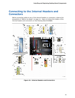
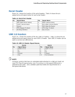
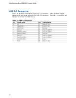
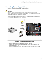
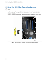
Intel Desktop Board DZ68BC Product Guide USB 3.0 Connector Figure 24, K shows the location of the USB 3.0 connector. Table 16 shows the pin assignments and signal names for the USB 3.0 connector. The USB 3.0 connector can be used to connect two USB devices. Table 16. USB 3.0 Connector Pin Signal Name 10 ID 9 IntA_P1_D+ 8 IntA_P1_D− 7 Ground 6 IntA_P1_SSTX+ 5 IntA_P1_SSTX− 4 Ground 3 IntA_P1_SSRX+ 2 IntA_P1_SSRX− 1 Vbus Pin Signal Name 11 IntA_P2_D+ 12 IntA_P2_D− 13 Ground 14 IntA_P2_SSTX+ 15 IntA_P2_SSTX− 16 Ground 17 IntA_P2_SSRX+ 18 IntA_P2_SSRX− 19 Vbus 20 Key (no pin) 54
-
 1
1 -
2
-
3
-
4
-
5
-
6
-
7
-
8
-
9
-
10
-
11
-
12
-
13
-
14
-
15
-
16
-
17
-
18
-
19
-
20
-
21
-
22
-
23
-
24
-
25
-
26
-
27
-
28
-
29
-
30
-
31
-
32
-
33
-
34
-
35
-
36
-
37
-
38
-
39
-
40
-
41
-
42
-
43
-
44
-
45
-
46
-
47
-
48
-
 49
49 -
 50
50 -
 51
51 -
 52
52 -
 53
53 -
 54
54 -
 55
55 -
 56
56 -
 57
57 -
 58
58 -
 59
59 -
60
-
61
-
62
-
63
-
64
-
65
-
66
-
67
-
68
-
69
-
70
-
71
-
72
-
73
-
74
-
75
-
76
-
77
-
78
-
79
-
80
-
81
-
82
-
83
-
84
-
85
-
86
-
87
-
88
 |
 |

Intel Desktop Board DZ68BC Product Guide
54
USB 3.0 Connector
Figure 24, K shows the location of the USB 3.0 connector.
Table 16 shows the pin
assignments and signal names for the USB 3.0 connector.
The USB 3.0 connector can
be used to connect two USB devices.
Table 16. USB 3.0 Connector
Pin
Signal Name
Pin
Signal Name
10
ID
11
IntA_P2_D+
9
IntA_P1_D+
12
IntA_P2_D
−
8
IntA_P1_D
−
13
Ground
7
Ground
14
IntA_P2_SSTX+
6
IntA_P1_SSTX+
15
IntA_P2_SSTX
−
5
IntA_P1_SSTX
−
16
Ground
4
Ground
17
IntA_P2_SSRX+
3
IntA_P1_SSRX+
18
IntA_P2_SSRX
−
2
IntA_P1_SSRX
−
19
Vbus
1
Vbus
20
Key (no pin)