Intel DZ68BC Product Guide - Page 29
Table 5., Board Status LEDs, Location of the Diagnostic LEDs, Desktop Board Features
 |
View all Intel DZ68BC manuals
Add to My Manuals
Save this manual to your list of manuals |
Page 29 highlights
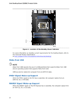
Desktop Board Features Table 5. Board Status LEDs (continued) Item/Callout in Figure 6 J Activity Option ROM Initialization LED Color Green K OS Start L IERR#_LED M PME#_LED Green Red Red Description This LED will flash when the option ROM activity starts. Then the LED will stay on when option ROM initialization is complete. Just before the BIOS transfers control to the operating system, this LED will light and stay on. Figure 6. Location of the Diagnostic LEDs 29
-
 1
1 -
2
-
3
-
4
-
5
-
6
-
7
-
8
-
9
-
10
-
11
-
12
-
13
-
14
-
15
-
16
-
17
-
18
-
19
-
20
-
21
-
22
-
23
-
 24
24 -
 25
25 -
 26
26 -
 27
27 -
 28
28 -
 29
29 -
 30
30 -
 31
31 -
 32
32 -
 33
33 -
 34
34 -
35
-
36
-
37
-
38
-
39
-
40
-
41
-
42
-
43
-
44
-
45
-
46
-
47
-
48
-
49
-
50
-
51
-
52
-
53
-
54
-
55
-
56
-
57
-
58
-
59
-
60
-
61
-
62
-
63
-
64
-
65
-
66
-
67
-
68
-
69
-
70
-
71
-
72
-
73
-
74
-
75
-
76
-
77
-
78
-
79
-
80
-
81
-
82
-
83
-
84
-
85
-
86
-
87
-
88
 |
 |

Desktop Board Features
29
Table 5.
Board Status LEDs
(continued)
Item/Callout
in Figure 6
Activity
LED
Color
Description
J
Option ROM Initialization
Green
This LED will flash when the option
ROM activity starts.
Then the LED will
stay on when option ROM initialization
is complete.
K
OS Start
Green
Just before the BIOS transfers control
to the operating system, this LED will
light and stay on.
L
IERR#_LED
Red
M
PME#_LED
Red
Figure 6.
Location of the Diagnostic LEDs