Intel DZ68BC Product Guide - Page 57
Connecting Power Supply Cables
 |
View all Intel DZ68BC manuals
Add to My Manuals
Save this manual to your list of manuals |
Page 57 highlights
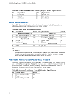
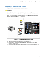
Installing and Replacing Desktop Board Components Connecting Power Supply Cables Figure 27 shows the location of the power connectors. CAUTION Failure to use an appropriate power supply and/or not connecting the 12 V (Figure 27, A) power connector to the Desktop Board may result in damage to the board or the system may not function properly. The 2 x 12 pin main power connector (Figure 27, B) is backwards compatible with ATX12V power supplies with 2 x 10 connectors. Figure 27. Connecting Power Supply Cables 1. Observe the precautions in "Before You Begin" on page 31. 2. Connect the 12 V processor core voltage power supply cable to the 2 x 4 pin connector (Figure 27, A). 3. Connect the main power supply cable to the 2 x 12 pin connector (Figure 27, B). 57
-
 1
1 -
2
-
3
-
4
-
5
-
6
-
7
-
8
-
9
-
10
-
11
-
12
-
13
-
14
-
15
-
16
-
17
-
18
-
19
-
20
-
21
-
22
-
23
-
24
-
25
-
26
-
27
-
28
-
29
-
30
-
31
-
32
-
33
-
34
-
35
-
36
-
37
-
38
-
39
-
40
-
41
-
42
-
43
-
44
-
45
-
46
-
47
-
48
-
49
-
50
-
51
-
 52
52 -
 53
53 -
 54
54 -
 55
55 -
 56
56 -
 57
57 -
 58
58 -
 59
59 -
 60
60 -
 61
61 -
 62
62 -
63
-
64
-
65
-
66
-
67
-
68
-
69
-
70
-
71
-
72
-
73
-
74
-
75
-
76
-
77
-
78
-
79
-
80
-
81
-
82
-
83
-
84
-
85
-
86
-
87
-
88
 |
 |
