Intel DZ68ZV Product Guide for Intel Desktop Board DZ68ZV - Page 13
Table 2. Intel Desktop Board DZ68ZV Components, Desktop Board Features, Label, Description
 |
View all Intel DZ68ZV manuals
Add to My Manuals
Save this manual to your list of manuals |
Page 13 highlights
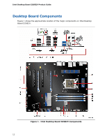
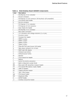
Desktop Board Features Table 2. Intel Desktop Board DZ68ZV Components Label A B C D E F G H I J K L M N O P Q R S T U V W X Y Z AA BB CC DD EE FF GG HH II JJ Description PCI Express 2.0 x1 connector PCI bus connector PCI Express 2.0 x16 connector (x8 electrical; x16 compatible) Front panel audio header PCI bus connector PCI Express 2.0 x1 connector PCI Express 2.0 x16 connector Rear chassis fan header PCI Express 2.0 x1 connector Back panel connectors 12 V processor core voltage connector (2 x 4 pin) Processor socket Processor fan header DIMM 3 socket DIMM 1 socket DIMM 4 socket DIMM 2 socket Alternate front panel power LED header Main power connector (2 x 12 pin) POST code LED display Onboard reset button Onboard power button Speaker Front chassis fan header Battery Serial ATA (SATA) connectors BIOS configuration jumper block Back panel CIR transmitter (output) header Front panel CIR receiver (input) header USB 2.0 headers Chassis intrusion header IEEE 1394a header Front panel header Diagnostic LEDs S/PDIF header Auxiliary chassis fan header 13
-
 1
1 -
2
-
3
-
4
-
5
-
6
-
7
-
 8
8 -
 9
9 -
 10
10 -
 11
11 -
 12
12 -
 13
13 -
 14
14 -
 15
15 -
 16
16 -
 17
17 -
 18
18 -
19
-
20
-
21
-
22
-
23
-
24
-
25
-
26
-
27
-
28
-
29
-
30
-
31
-
32
-
33
-
34
-
35
-
36
-
37
-
38
-
39
-
40
-
41
-
42
-
43
-
44
-
45
-
46
-
47
-
48
-
49
-
50
-
51
-
52
-
53
-
54
-
55
-
56
-
57
-
58
-
59
-
60
-
61
-
62
-
63
-
64
-
65
-
66
-
67
-
68
-
69
-
70
-
71
-
72
-
73
-
74
-
75
-
76
-
77
-
78
-
79
-
80
-
81
-
82
-
83
-
84
-
85
-
86
-
87
-
88
-
89
-
90
-
91
-
92
 |
 |
