Intermec PX4i Industrial/Serial Interface Kit Installation Instructions - Page 23
Serial Interface, upside down see front end markings - driver
 |
View all Intermec PX4i manuals
Add to My Manuals
Save this manual to your list of manuals |
Page 23 highlights
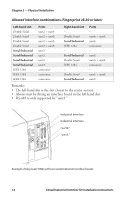
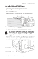
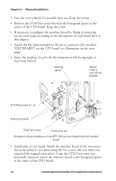
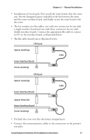
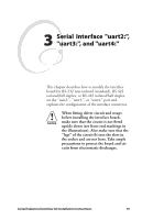
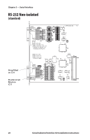
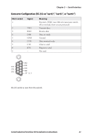
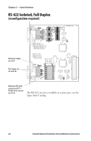
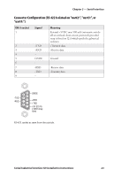
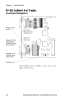
3 Serial Interface "uart2:", "uart3:", and "uart4:" This chapter describes how to modify the interface board for RS-232 non-isolated (standard), RS-422 isolated/full duplex, or RS-485 isolated/half duplex on the "uart2:", "uart3:", or "uart4:" port and explains the configuration of the interface connector. When fitting driver circuit and straps before installing the interface board, make sure that the circuit is not fitted upside down (see front end markings in the illustrations). Also make sure that the "legs" of the circuit fit into the slots in the socket and are not bent. Take ample precautions to protect the board and circuits from electrostatic discharges. Serial/Industrial Interface Kit Installation Instructions 19
-
 1
1 -
2
-
3
-
4
-
5
-
6
-
7
-
8
-
9
-
10
-
11
-
12
-
13
-
14
-
15
-
16
-
17
-
 18
18 -
 19
19 -
 20
20 -
 21
21 -
 22
22 -
 23
23 -
 24
24 -
 25
25 -
 26
26 -
 27
27 -
 28
28 -
29
-
30
-
31
-
32
-
33
-
34
-
35
-
36
-
37
-
38
-
39
-
40
 |
 |

Serial/Industrial Interface Kit Installation Instructions
19
3
Serial Interface "uart2:",
"uart3:", and "uart4:"
°is chapter describes how to modify the interface
board for RS-232 non-isolated (standard), RS-422
isolated/full duplex, or RS-485 isolated/half duplex
on the "uart2:", "uart3:", or "uart4:" port and
explains the configuration of the interface connector.
When fitting driver circuit and straps
before installing the interface board,
make sure that the circuit is not fitted
upside down (see front end markings in
the illustrations). Also make sure that the
“legs” of the circuit fit into the slots in
the socket and are not bent. Take ample
precautions to protect the board and cir-
cuits from electrostatic discharges.