Intermec PX4i Industrial/Serial Interface Kit Installation Instructions - Page 32
Digital Opto
 |
View all Intermec PX4i manuals
Add to My Manuals
Save this manual to your list of manuals |
Page 32 highlights
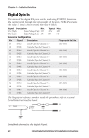
Chapter 4 - Industrial Interface Digital Opto In The status of the digital IN ports can be read using PORTIN functions. If a current is led through the optocoupler of the port, PORTIN returns the value -1 (true), else it returns the value 0 (false). Signal Description Min. Vin [High] Input Voltage High 10V Vin [Low] Input Voltage Low -1V Connector Configuration Typical Max. 24V 40V 0V 1V Pin Signal Description 10 IN1A Anode Opto In Channel 1 + 40 IN1K Cathode Opto In Channel 1 - 26 IN2A Anode Opto In Channel 2 + 11 IN2K Cathode Opto In Channel 2 - 41 IN3A Anode Opto In Channel 3 + 27 IN3K Cathode Opto In Channel 3 - 12 IN4A Anode Opto In Channel 4 + 42 IN4K Cathode Opto In Channel 4 - 28 IN5A Anode Opto In Channel 5 + 13 IN5K Cathode Opto In Channel 5 - 43 IN6A Anode Opto In Channel 6 + 29 IN6K Cathode Opto In Channel 6 - 14 IN7A Anode Opto In Channel 7 + 44 IN7K Cathode Opto In Channel 7 - 30 IN8A Anode Opto In Channel 8 + 15 IN8K Cathode Opto In Channel 8 - Fingerprint Ref. No. 101 (301) 102 (302) 103 (303) 104 (304) 105 (305) 106 (306) 107 (307) 108 (308) The Fingerprint reference numbers inside the parentheses refer to a second Serial/Industrial interface board. INA INK GND Simplified schematics of a digital IN port. 28 Serial/Industrial Interface Kit Installation Instructions
-
 1
1 -
2
-
3
-
4
-
5
-
6
-
7
-
8
-
9
-
10
-
11
-
12
-
13
-
14
-
15
-
16
-
17
-
18
-
19
-
20
-
21
-
22
-
23
-
24
-
25
-
26
-
 27
27 -
 28
28 -
 29
29 -
 30
30 -
 31
31 -
 32
32 -
 33
33 -
 34
34 -
 35
35 -
 36
36 -
 37
37 -
38
-
39
-
40
 |
 |
