Intermec PX4i Industrial/Serial Interface Kit Installation Instructions - Page 33
Digital Opto Out
 |
View all Intermec PX4i manuals
Add to My Manuals
Save this manual to your list of manuals |
Page 33 highlights
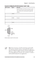
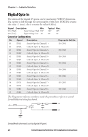
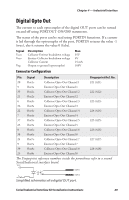
Chapter 4 - Industrial Interface Digital Opto Out The current to each optocoupler of the digital OUT ports can be turned on and off using PORTOUT ON/OFF statements. The status of the ports can be read using PORTIN functions. If a current is led through the optocoupler of the port, PORTIN returns the value -1 (true), else it returns the value 0 (false). Signal Vceo Veco Vog Description Collector-Emitter breakdown voltage Emitter-Collector breakdown voltage Collector Current Output to ground (optocoupler) Max. 35V 6V 15 mA 100V Connector Configuration Pin Signal Description Fingerprint Ref. No. 20 Out1c Collector Opto Out Channel 1 221 (421) 5 Out1e Emitter Opto Out Channel 1 35 Out2c Collector Opto Out Channel 2 222 (422) 21 Out2e Emitter Opto Out Channel 2 6 Out3c Collector Opto Out Channel 3 223 (423) 36 Out3e Emitter Opto Out Channel 3 22 Out4c Collector Opto Out Channel 4 224 (424) 7 Out4e Emitter Opto Out Channel 4 37 Out5c Collector Opto Out Channel 5 225 (425) 23 Out5e Emitter Opto Out Channel 5 8 Out6c Collector Opto Out Channel 6 226 (426) 38 Out6e Emitter Opto Out Channel 6 24 Out7c Collector Opto Out Channel 7 227 (427) 9 Out7e Emitter Opto Out Channel 7 39 Out8c Collector Opto Out Channel 8 228 (428) 25 Out8e Emitter Opto Out Channel 8 The Fingerprint reference numbers inside the parentheses refer to a second Serial/Industrial interface board. VCC OUTc OUTa Simplified schematics of a digital OUT port. Serial/Industrial Interface Kit Installation Instructions 29
-
 1
1 -
2
-
3
-
4
-
5
-
6
-
7
-
8
-
9
-
10
-
11
-
12
-
13
-
14
-
15
-
16
-
17
-
18
-
19
-
20
-
21
-
22
-
23
-
24
-
25
-
26
-
27
-
 28
28 -
 29
29 -
 30
30 -
 31
31 -
 32
32 -
 33
33 -
 34
34 -
 35
35 -
 36
36 -
 37
37 -
 38
38 -
39
-
40
 |
 |
