Invacare CRFTI Owners Manual - Page 57
Wheel Locks, Replacing/Adjusting the Wheel Locks, Replacing the Wheel Lock
 |
View all Invacare CRFTI manuals
Add to My Manuals
Save this manual to your list of manuals |
Page 57 highlights
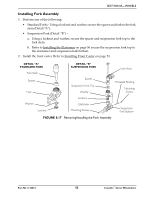
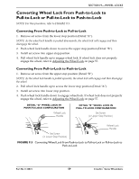
SECTION 9-WHEEL LOCKS SECTION 9-WHEEL LOCKS ƽ WARNING After any adjustments, repair or service and before use, make sure all attaching hardware is tightened securely - otherwise injury or damage may result. Replacing/Adjusting the Wheel Locks ƽ WARNING If wheel locks do not hold the occupied wheelchair in place contact a qualified technician - otherwise injury or damage may occur. NOTE: For this procedure, refer to FIGURE 9.1 on page 58. NOTE: Before adjusting or replacing wheel locks, ensure that the tires are inflated to the recommended psi on the sidewall of the tire. Replacing the Wheel Lock 1. Remove the two mounting screws and remove the existing wheel lock from the wheelchair. 2. Using the two mounting screws, install the new wheel lock. Securely tighten. Adjusting the Wheel Lock 1. Engage the wheel locks. NOTE: Any wheel lock adjustment should embed the wheel lock shoe at least 3/16‐inch into the pneumatic tire (1/8‐inch for urethane wheels) when engaged. 2. If necessary, loosen the two mounting screws that secure the wheel locks to the wheelchair frame and adjust position of the wheel lock until the 3/16‐inch (1/8‐inch for urethane wheels) measurement is obtained for correct wheel lock adjustment. 3. Securely tighten the two mounting screw(s). 4. Engage the wheel locks and push against the wheelchair and determine if the wheel locks engage the wheel locks enough to hold the wheelchair. 5. Repeat the above procedures until the wheel locks hold the wheelchair. Part No 1134872 57 Crossfire™Series Wheelchairs
-
 1
1 -
2
-
3
-
4
-
5
-
6
-
7
-
8
-
9
-
10
-
11
-
12
-
13
-
14
-
15
-
16
-
17
-
18
-
19
-
20
-
21
-
22
-
23
-
24
-
25
-
26
-
27
-
28
-
29
-
30
-
31
-
32
-
33
-
34
-
35
-
36
-
37
-
38
-
39
-
40
-
41
-
42
-
43
-
44
-
45
-
46
-
47
-
48
-
49
-
50
-
51
-
 52
52 -
 53
53 -
 54
54 -
 55
55 -
 56
56 -
 57
57 -
 58
58 -
 59
59 -
 60
60 -
 61
61 -
 62
62 -
63
-
64
 |
 |
