Invacare CRFTI Owners Manual - Page 58
Changing Wheel Lock Handle Position,
 |
View all Invacare CRFTI manuals
Add to My Manuals
Save this manual to your list of manuals |
Page 58 highlights
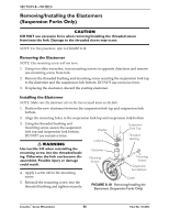
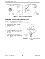
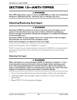
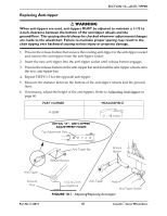
SECTION 9-WHEEL LOCKS Push-to-Lock or Pull-to-Lock Wheel Locks Mounting Screws 3/16 inch (1/8-inch) Under Mount Wheel Lock Mounting Screws 3/16 inch (1/8-inch) Wheel Lock Tire Wheel Lock Shoe Wheel Lock Tire FIGURE 9.1 Replacing/Adjusting the Wheel Locks Wheel Lock Shoe Changing Wheel Lock Handle Position NOTE: For this procedure, refer to FIGURE 9.2. 1. Loosen, but DO NOT remove, the rear handle mounting screw. 2. Remove the front handle mounting screw and locknut. Wheel lock Handle 3. Align the front handle mounting hole with one of three desired mounting positions on the wheel lock. 4. Using the front handle mounting screw and locknut, secure the handle to the wheel lock. 5. Securely tighten the front and rear handle mounting screws and locknuts. 6. Repeat STEPS 1‐5 on remaining wheel lock handle. Mounting Positions Rear Handle Mounting Screw Front Handle Mounting Screw and Locknut FIGURE 9.2 Changing Wheel Lock Handle Position Crossfire™Series Wheelchairs 58 Part No 1134872
-
 1
1 -
2
-
3
-
4
-
5
-
6
-
7
-
8
-
9
-
10
-
11
-
12
-
13
-
14
-
15
-
16
-
17
-
18
-
19
-
20
-
21
-
22
-
23
-
24
-
25
-
26
-
27
-
28
-
29
-
30
-
31
-
32
-
33
-
34
-
35
-
36
-
37
-
38
-
39
-
40
-
41
-
42
-
43
-
44
-
45
-
46
-
47
-
48
-
49
-
50
-
51
-
52
-
 53
53 -
 54
54 -
 55
55 -
 56
56 -
 57
57 -
 58
58 -
 59
59 -
 60
60 -
 61
61 -
 62
62 -
 63
63 -
64
 |
 |
